Welcome to Taxo Tape
What Is a Thermal Management System? Components & Design Guide
Introduction
A thermal interface material is only one link in a longer chain. Heat has to be generated, absorbed, moved, and eventually released to the surrounding environment — and every one of those steps involves a different component making its own contribution to whether a device stays within safe operating temperature or not.
This guide looks at that full chain rather than any single link in it. Where a TIM-focused discussion covers the material that bridges a component to a heat sink, a thermal management system covers everything working together to get heat out of a device in the first place: the heat sinks and spreaders, the fans or liquid loops moving air or fluid, the sensors monitoring temperature in real time, and the TIMs bridging each of those pieces to the components they're protecting. Understanding how these pieces fit together — and when a design calls for passive components versus active ones — is what separates a thermal system that just barely works from one engineered to hold up over a product's full service life.
What Is a Thermal Management System?
A thermal management system is the combination of technologies and components that work together to control, move, and release the heat a device generates during operation. Its purpose is straightforward: keep temperature-sensitive components within a safe operating range long enough, and consistently enough, to deliver the performance and service life the product is designed for.
Every thermal management system, regardless of complexity, performs three core functions. It absorbs heat at the source — at an IC, a battery cell, a power transistor — where that heat is actually generated. It transfers that heat away from the source toward a heat spreader, sink, or enclosure wall. And it dissipates that heat into the surrounding environment through conduction, convection, or radiation, completing the path from component to ambient air.
Thermal management approaches generally fall into two categories. Passive systems rely on materials and structures — thermal pads, heat sinks, natural convection — with no external energy input required. Active systems add powered components — fans, blowers, liquid pumps — to accelerate heat removal beyond what passive elements alone can achieve. Many current designs combine both, using a hybrid approach to balance thermal performance against cost, space, and power budget.
Key Components of a Thermal Management System
A complete thermal management system draws on several distinct component categories, each handling a different part of the heat removal path.
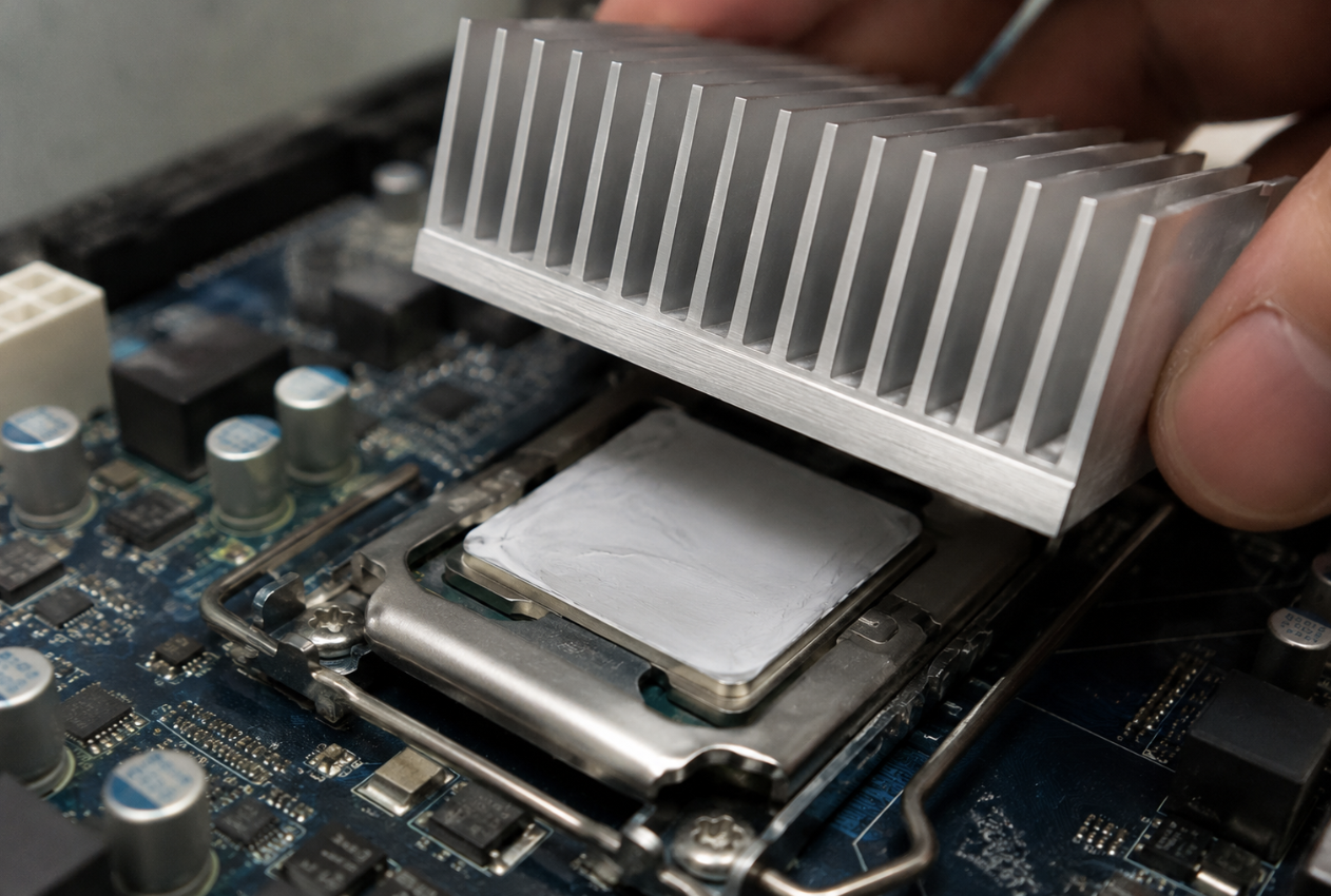
Thermal interface materials (TIMs) fill the microscopic gaps between mating surfaces — a semiconductor and its heat sink, a battery cell and a cooling plate — reducing thermal resistance at the interface and allowing heat to move more efficiently into the rest of the system. TIM selection is a substantial topic in its own right, covered in detail in An Introduction to Thermal Interface Materials.
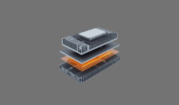
Heat sinks and spreaders — typically aluminum or copper structures — absorb heat and dissipate it through increased surface area, often shaped with fins or plates to maximize contact with moving or still air.
Fans and blowers drive active cooling by moving air across hot surfaces to accelerate convective heat transfer. Blowers see particular use where directed airflow or higher static pressure is needed, such as in enclosed equipment or industrial environments where natural airflow alone isn't sufficient.
Heat pipes and vapor chambers are sealed structures that use phase-change principles to move heat rapidly from one location to another, often across distances or geometries that a solid heat sink can't bridge efficiently. These see regular use in high-power-density designs — CPUs, power electronics, EV battery modules — where heat needs to move quickly away from a concentrated source.
Liquid cooling systems offer high thermal capacity for applications generating substantial heat loads. Coolant circulates through cold plates or channels to extract heat directly from temperature-sensitive components, a method common in high-performance computing, energy storage systems, and power electronics where air cooling alone can't keep pace with the heat load.
Temperature sensors and control electronics monitor real-time conditions and adjust the system's response accordingly — ramping fan speed, throttling load, or triggering protective shutdown when temperatures approach a safety threshold. This monitoring layer is what turns a static set of cooling components into a system that responds to actual operating conditions rather than worst-case assumptions alone.
Passive vs. Active vs. Hybrid: Making the Trade-off
Choosing between passive, active, and hybrid approaches comes down to how much heat needs to move, how much space and budget are available to move it, and how much tolerance the design has for noise, power draw, and moving parts that can fail.
Passive cooling is the default starting point for compact systems with moderate heat loads — it's cost-effective, requires no maintenance, and introduces no additional points of failure. But passive approaches have a ceiling: once heat generation exceeds what natural convection and conduction alone can dissipate, no amount of heat sink surface area fully compensates, and the design needs an active assist.
Active cooling extends that ceiling substantially, but it comes with trade-offs of its own — power consumption, acoustic noise, and mechanical components (fans, pumps) that introduce their own reliability considerations over a product's service life. Active cooling tends to be the right call in high-power or tightly packed designs where passive dissipation simply can't keep pace with the heat load, regardless of how much thermal interface or heat sink optimization is applied upstream.
Hybrid systems — a heat sink paired with a fan, for example, or a passive spreader combined with a liquid loop for peak loads — let designers capture passive cooling's reliability and low power draw for baseline conditions while reserving active cooling for peak thermal demand. This approach is increasingly common in designs where power density varies significantly between idle and full-load operation, since it avoids running active cooling continuously when it's only needed intermittently.
Application Examples Across Industries
Thermal management needs shift considerably depending on the application, though the underlying component categories stay the same.
LED lighting systems concentrate significant heat in a small emitting area, typically addressed with thermal interface pads or PCM at the board-to-housing contact, aluminum base plates for conduction, and — in enclosed luminaires — fans or open airflow paths to support convection. See Thermal Interface Materials for LED Drivers for a closer look at TIM selection specific to LED driver circuits.
Battery packs, in EVs and stationary energy storage alike, rely on phase change materials to stabilize temperature through charge-discharge cycling, graphite or aluminum spreaders to distribute heat evenly across the pack, and — in larger systems — liquid cooling integrated directly into the pack structure.
Power inverters and converters operating continuously under variable load typically combine thermal pads at power module interfaces with extruded aluminum heat sinks, often supplemented by fans for forced-air cooling within the inverter enclosure.
Industrial control units and densely populated PCBs manage heat buildup with graphite sheets for lateral heat spreading, thermal gels to accommodate uneven component heights across the board, and controlled airflow or enclosure ventilation to maintain consistent heat removal across the assembly.
How to Design or Choose a Thermal Management System
Selecting the right thermal management approach starts with understanding how heat actually behaves in your specific design, not with picking components off a catalog page.
Assess thermal load and critical components. Identify where heat is actually generated — processors, MOSFETs, transformers, battery cells — and how much power each dissipates across the range of operating conditions the product will see, not just a single nominal load point.
Identify heat paths and dissipation surfaces. Map how heat needs to travel from each source to the surrounding environment. This means understanding the available surface area, mounting constraints, and airflow paths your mechanical design actually permits — a thermal solution that looks ideal on paper can be impractical once real enclosure geometry is factored in.
Select materials and technologies to match the thermal budget. Choose TIMs, heat sinks, or active cooling components based on the thermal budget established in the first step, along with design limitations and target cost. Electrical insulation requirements, mechanical stress tolerance, and ease of integration during assembly all factor into which specific components are practical, not just which ones would perform best in isolation.
Validate through prototyping and simulation. Datasheet values describe component performance under standardized test conditions, not your actual assembly. Thermal simulation tools combined with physical prototype testing — early in the development cycle, before design decisions are locked in — remain the most reliable way to confirm a thermal system will perform as intended once it's built.
Where TIMs Fit Into the Bigger Picture
Every component covered in this guide depends on the interfaces between them working correctly. A heat sink with excellent fin design still underperforms if the thermal pad connecting it to the component beneath is poorly matched to the gap it needs to fill. A liquid cooling loop moves heat efficiently through its channels, but the cold plate still needs a properly specified TIM at its contact point with the component it's cooling.
This is what makes TIM selection disproportionately important relative to its size and cost within the overall system: it's the interface layer sitting at nearly every junction in the heat removal path, and a poorly chosen TIM can undermine the performance of an otherwise well-engineered thermal system. For a closer look at how to evaluate and select TIMs for a specific application — material types, key selection parameters, and common selection mistakes — see An Introduction to Thermal Interface Materials.
Trends in Thermal Management Systems
Thermal management technology continues to evolve alongside the electronics it supports. There's increasing demand for lightweight, compact, and integrated solutions — particularly in EVs, wearable electronics, and portable power systems, where thermal components need to be thin and easy to assemble without compromising performance.
Electrification and rising power density across EVs, energy storage, 5G telecom, and edge computing continues to push systems toward carrying more power in tighter spaces, driving demand for higher-performance TIMs, more capable heat spreaders, and hybrid cooling systems able to handle rapid, localized heat spikes.
AI and IoT-enabled thermal monitoring is showing up in more designs, with sensors and predictive algorithms adjusting fan speed, coolant flow, or power draw in real time — improving efficiency and reducing energy waste relative to static, worst-case-assumption cooling strategies.
There's also a growing emphasis on sustainable materials and energy-efficient cooling — RoHS/REACH-compliant, halogen-free, and recyclable materials, alongside energy-efficient approaches like passive-first designs and variable-speed fans that reduce system-wide power consumption.
FAQ
Q: When does a design need active cooling instead of passive?
Passive cooling handles moderate heat loads reliably and without added cost or complexity, but it has a ceiling — once heat generation exceeds what natural convection and conduction can dissipate through the available surface area, no amount of heat sink optimization fully compensates. High-power or tightly packed designs, where passive dissipation can't keep pace with the heat load, generally require an active assist.
Q: What's the difference between a heat pipe and a liquid cooling system?
A heat pipe is a sealed, self-contained structure that uses phase-change principles to move heat rapidly between two points, with no external pump or power input required. A liquid cooling system actively circulates coolant through cold plates or channels using a pump, offering higher thermal capacity for applications generating substantial heat loads, at the cost of added complexity and a powered component that needs to remain reliable over the product's service life.
Q: Do all thermal management systems need temperature sensors?
Not necessarily — simple passive systems with predictable, steady-state heat loads can operate reliably without active monitoring. But any system using active cooling components, or operating across a wide range of load conditions, benefits from real-time temperature data to adjust fan speed, trigger protective measures, or optimize energy use rather than relying on worst-case design margins alone.
A thermal management system is only as strong as its weakest link, and that link is often an interface rather than a major component — the pad, gel, or paste connecting a heat source to whatever is meant to carry that heat away. Getting the system-level architecture right — matching passive, active, or hybrid approaches to actual thermal load, mapping realistic heat paths, and validating through prototyping rather than datasheet values alone — creates the foundation. Getting the TIM selection right at each interface within that architecture is what determines whether the system actually delivers the performance it was designed for.
For engineering teams developing power electronics, LED lighting, battery systems, or industrial controls, thermal strategy is worth treating as a core design consideration from the start, not a problem to solve after the mechanical layout is already fixed.
Contact TaxoTape® to discuss thermal interface materials for your system design →