Welcome to Taxo Tape
1K vs 2K Thermal Gap Fillers: Which Is Right for Your Power Electronics Design?
Thermal gap fillers rarely make it onto the critical path during early design reviews. They get selected late, often by matching a conductivity number on a datasheet, and the difference between a one-component and two-component system gets treated as a procurement detail rather than an engineering decision.
That's where problems start. A gap filler that works fine in prototype assembly can become a production bottleneck, a field reliability issue, or a rework nightmare — not because the thermal performance was wrong, but because the application format wasn't matched to the manufacturing environment.
This article breaks down the 1K vs. 2K distinction from a practical engineering standpoint: what it actually means, where the real performance differences lie, and how to match the right system to your specific application.
What "1K" and "2K" Actually Mean
The terms are borrowed from coating and adhesive chemistry, where "K" stands for Komponente (German for component). In gap filler products, the number simply tells you how many parts you're working with before application.
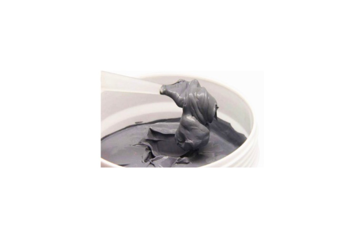
1K (one-component) gap fillers come ready to use. There's no mixing, no ratio to control, and no pot life to manage. Depending on the formulation, they may cure via moisture exposure, UV, or simply stay in a semi-cured, conformable state throughout their service life. The last category — often called "form-in-place" or non-curing gap fillers — is probably the most common in electronics thermal management. You dispense or place it, compress it between surfaces, and it conforms to the interface geometry under assembly load.
2K (two-component) gap fillers consist of a base and a curing agent, stored separately and mixed immediately before application. The curing reaction — typically platinum-catalyzed addition cure for silicone-based systems — is triggered by combining the two parts at a specified ratio, usually 1:1 or 1:10 by weight or volume depending on the product. The mixed material is liquid or semi-liquid, flows into gaps and around components, then cures to a soft elastomeric solid either at room temperature or with applied heat.
Why does this cause confusion in practice?
Because the terminology isn't standardized across suppliers. Some manufacturers label non-curing conformable pads as "1K dispensable gap fillers." Others use "gap filler" interchangeably with "gel" or "potting compound" in their catalogs. When you're reviewing an RFQ response or comparing quotes from two suppliers, you may be looking at fundamentally different application systems under the same product category name.
The safest approach: always ask for the application method, cure mechanism, and whether mixing equipment is required — before comparing conductivity values.
How They Compare: A Side-by-Side Breakdown
The table below reflects general industry ranges. Actual values vary significantly by product line and filler loading — always validate against specific TDS documents before finalizing a design.
| Parameter | 1K Gap Filler | 2K Gap Filler |
|---|---|---|
| Thermal Conductivity | ~1.5 – 6.0 W/m·K | ~3.0 – 8.0 W/m·K |
| Application Method | Dispensing, stencil, manual placement | Meter-mix dispensing, static mixer |
| Cure Requirement | None / moisture / UV (product-dependent) | Room temperature or heat-accelerated |
| Pot Life After Mixing | N/A | Typically 30 min – 4 hrs |
| Conformability | High (especially non-curing types) | Moderate to high (post-cure) |
| Typical BLT Range | 0.25 – 5.0 mm | 0.5 – 6.0 mm (flow-fill capable) |
| Production Volume Fit | Low to medium | Medium to high |
A few parameters worth unpacking:
Thermal conductivity ceiling. 2K systems generally reach higher conductivity values because the liquid state before cure allows higher filler loading (typically aluminum oxide, boron nitride, or zinc oxide particles) without sacrificing processability. In a pre-formed 1K pad, high filler loading can compromise conformability, which counteracts the conductivity gain at the interface. For applications above ~6 W/m·K, 2K systems are usually the practical path.
Contact resistance vs. bulk conductivity. This is the distinction that gets overlooked most often. A 3 W/m·K gap filler with excellent surface conformability can outperform a 6 W/m·K product with poor wetting at the interface. Total thermal resistance across the junction — not conductivity alone — is what matters for your thermal budget. This is particularly relevant when comparing a highly conformable 1K gel against a stiffer 2K system.
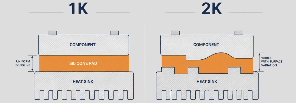
Bondline thickness control. 2K liquid-dispensed systems can flow into variable-height gaps and self-level, which is an advantage when component height tolerances are loose. 1K pre-formed materials require more careful stack-up tolerance management to ensure adequate compression without over-stressing components.
Where 1K Gap Fillers Have the Edge
The strongest case for a 1K system comes down to simplicity and process robustness.
Prototyping and design validation are the most obvious fit. With no mixing ratio to control and no pot life to manage, engineers can apply material consistently across a small number of assemblies without specialized equipment. Swapping thicknesses or conductivity grades between builds is fast. For qualification testing — where you may be running thermal cycles across three or four material variants — 1K formats eliminate one significant variable from the process.
Field service and repair is another area where 1K wins decisively. A two-part system is effectively unusable in a field maintenance context. Managing metering equipment, controlling mix ratio, and working within a pot life window during a board swap in an inverter cabinet is not realistic. Pre-cut 1K pads or dispensed gels are applied in seconds, require no cure time before reassembly, and leave no mixed-material waste to manage.
Complex or irregular geometries that require manual placement benefit from the handling characteristics of formed 1K materials. A semi-cured silicone pad can be pressed into a recessed cavity, wrapped around a component, or layered across an uneven surface in ways that a dispensed liquid — even a low-viscosity 2K system — can't reliably replicate without tooling or fixturing.
Sensitive components under compression load are another consideration. Non-curing 1K gap fillers maintain a degree of compliance throughout their service life, which means they continue to absorb mechanical stress from CTE mismatches and thermal cycling without transmitting rigid loading to solder joints or fragile packages. Once a 2K system has cured to an elastomeric solid, its mechanical behavior is more fixed — generally still compliant, but less accommodating than a non-cured interface material.
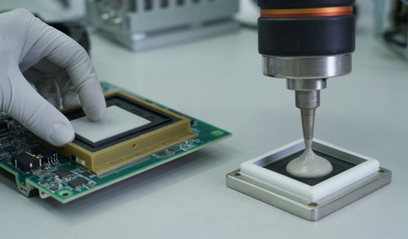
One practical note: 1K dispensable gap fillers require a compatible dispensing valve and pressure-feed system if used in production. "No mixing" doesn't mean "no equipment" — high-viscosity filled gels can be demanding on dispensing hardware, and needle selection matters for consistent bead geometry.
Where 2K Gap Fillers Make More Sense
The case for a 2K system is strongest when production throughput, thermal performance ceiling, or geometric complexity push beyond what a pre-formed or dispensed 1K material can reliably deliver.
High-volume automated assembly lines are the natural home for 2K gap fillers. With a meter-mix dispensing system controlling the mix ratio and shot volume, material application becomes a repeatable, auditable process step. Cycle time per unit drops, operator variability is eliminated, and the dispensed bead geometry can be programmed to match the component footprint exactly. For manufacturers running hundreds or thousands of units per shift — EV charger power modules, industrial UPS boards, three-phase inverter assemblies — this process consistency justifies the equipment investment.
Higher thermal conductivity requirements increasingly point toward 2K. When your thermal simulation shows that the gap filler interface needs to stay below a specific resistance budget and a 1K product at 4–5 W/m·K isn't enough headroom, the 6–8 W/m·K range available in 2K formulations becomes the practical path forward. This comes up regularly in high-power density designs: IGBT modules in motor drives, SiC switching stages in fast chargers, or synchronous rectifiers in server power supplies where junction temperatures are already running close to their limits.
Structural bonding combined with thermal management is a scenario where 2K has a distinct functional advantage. Some 2K gap filler formulations develop meaningful adhesive strength after cure, allowing the material to serve simultaneously as a thermal interface and a mechanical attachment — eliminating a separate bonding step for heat sink attachment or PCB retention in vibration-prone enclosures. This is relevant for industrial equipment mounted on machinery or in transportation applications where board-level vibration is a real operating condition.
Variable or unpredictable gap heights across a board assembly also favor 2K liquid systems. When component height tolerance stack-up means your actual bondline thickness could land anywhere between 0.8 mm and 2.5 mm across a production run, a dispensed liquid that flows and conforms to whatever gap exists provides more process margin than a pre-formed pad cut to a fixed thickness.
One constraint worth planning around: 2K systems require investment in metering and mixing equipment, and that equipment needs regular maintenance and purging. Mixed material left in the static mixer will cure and block the line. For low-volume or intermittent production, the equipment overhead can outweigh the material performance advantages.
Key Selection Criteria for Power Electronics Designers
Conductivity and component type get most of the attention during material selection, but several other parameters have equal or greater influence on whether a gap filler actually performs as expected in service.
Bondline thickness tolerance. The specified conductivity of a gap filler is calculated at a defined bondline thickness — typically 1.0 mm or as tested per ASTM D5470. If your actual BLT under compression differs significantly from that test condition, your real-world thermal resistance will differ too. Understand your component height variation across the board and confirm the material's performance curve across your expected BLT range, not just at the datasheet test point.
Operating temperature range and long-term stability. Most silicone-based gap fillers are rated for continuous operation from –40°C to 150°C or beyond, which covers the majority of industrial power electronics environments. What matters more for long-term reliability is how the material behaves over thousands of thermal cycles — whether it maintains contact pressure, resists compression set, and doesn't bleed filler particles or silicone oil onto adjacent components or connector contacts. Ask for thermal aging data, not just the initial conductivity figure.
Electrical insulation requirements. In most power electronics applications, the gap filler sits between a component case and a grounded heat sink, meaning it needs to provide electrical isolation. Verify volume resistivity (typically >10¹⁰ Ω·cm for insulating grades) and dielectric strength (commonly 10–25 kV/mm range for BN-filled or aluminum oxide-filled materials). If your design uses an electrically conductive heat spreader or has unusual creepage requirements, this needs to be part of the material selection criteria from the start, not a post-design check.
Compression load on components. Gap fillers are assembled under compression, and that compression load is transmitted to whatever sits beneath them. For ceramic capacitors, crystal oscillators, or fine-pitch BGA packages, excessive compressive load causes mechanical failures that don't always show up immediately — they appear during thermal cycling or vibration testing. Understand the assembly compression force your chosen material requires, and confirm it's within acceptable limits for your most sensitive component.
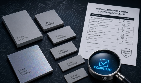
Certification and compliance. For equipment sold into industrial, medical, or EV markets, UL 94 flame rating (typically V-0), RoHS compliance, and REACH status are baseline requirements. Some applications add IEC or regional safety certifications that constrain material options further. Pull the full compliance documentation before shortlisting, not at the approved vendor stage.
Common Specification Mistakes to Avoid
Most gap filler selection errors don't come from choosing the wrong conductivity grade. They come from treating the material as a commodity and skipping the application-level questions.
Optimizing conductivity while ignoring interface contact resistance. A thermally conductive material that doesn't wet the surface properly delivers a fraction of its rated performance. Conductivity measured in a laboratory fixture under controlled pressure doesn't equal conductivity at your specific interface under your specific assembly load. If you're comparing two products and one is rated 5 W/m·K while the other is 4 W/m·K, but the lower-rated product has significantly lower contact resistance at your bondline conditions, the 4 W/m·K material may produce better thermal results in your assembly.
Underestimating pot life constraints in manual or semi-manual assembly. Engineers evaluating 2K materials often focus on the technical datasheet and overlook the production floor reality. If your assembly process involves manual placement steps, inspection holds, or intermittent production scheduling, a pot life of 45 minutes can become a consistent source of scrapped material and rework. Either confirm your line can work within the window or consider whether a 1K alternative — even at a slight thermal performance trade-off — delivers better total process yield.
Assuming all 2K products share the same mix ratio and equipment compatibility. A switch from one 2K gap filler to another — even between products with similar specs — can require recalibration of mix ratio, adjustment of dispense pressure, or a different static mixer geometry. Treating 2K materials as drop-in substitutes without a process validation step has caused more than a few production quality escapes.
Selecting a 1K dispensable product without confirming dispensing system compatibility. High-viscosity thermally filled gels can be abrasive on dispensing valves and may require heated reservoirs, specific needle gauges, and higher dispensing pressure than standard adhesives. Confirm compatibility with your existing dispensing hardware before committing to a material in production quantities.
Leaving gap filler selection to the end of the design cycle. When a gap filler is chosen after the PCB layout and enclosure design are locked, the options narrow considerably. Involving thermal interface material requirements early — specifying target BLT range, acceptable compression load, and electrical isolation requirements at the schematic stage — keeps the full range of material solutions available and avoids late-stage design changes.
Narrowing the Choice: Three Questions
If you're still working through the 1K vs. 2K decision, these three questions will cover most cases:
1. What is your production volume and do you have meter-mix dispensing equipment?If the answer is low volume or no equipment, start with 1K. The process simplicity advantage is real and significant.
2. Does your thermal budget require conductivity above 5–6 W/m·K?If yes, 2K formulations are the more practical path to that performance level.
3. Is field serviceability or repair a design requirement?If the assembly will ever be serviced in the field, 1K is the only workable format.
For applications where none of these questions give a clear answer — mid-volume production, moderate thermal requirements, controlled manufacturing environment — the decision often comes down to process qualification data and supplier application support. Requesting application-specific samples and testing both formats under your actual assembly conditions is more reliable than any datasheet comparison.