Welcome to Taxo Tape
Top 5 Thermal Interface Materials for EV & ESS Batteries
Introduction
Battery packs in electric vehicles and energy storage systems operate under conditions that consumer electronics rarely encounter: sustained high current draw, deep charge-discharge cycles, and — in the case of ESS — years of continuous outdoor exposure. Under these conditions, the thermal interface material sitting between a cell, a module, and a cooling structure is not a minor bill-of-materials line item. It's one of the factors that determines whether a pack hits its design life or fails early.
For engineers specifying TIMs in EV or ESS applications, the challenge is less about finding "the most conductive material" and more about matching material properties to a specific thermal path, mechanical constraint, and manufacturing process. This article walks through the five TIM categories most commonly used in battery pack design, how they compare on the properties that matter for this application, and the selection criteria that typically separate a good fit from a costly rework.
Why TIM Selection Matters in EV & ESS Battery Packs
Every charge and discharge cycle generates heat through internal resistance and electrochemical reactions inside the cell. In a single-cell consumer device, this heat has room to dissipate. In a densely packed EV module or a stacked ESS rack, dozens or hundreds of cells generate heat simultaneously, and the thermal path between each cell and the cooling structure — typically a cold plate or liquid-cooled chassis — becomes the limiting factor for how effectively that heat gets removed.
When this path is poorly managed, three failure modes tend to show up, in roughly this order of severity:
Uneven cell temperatures — cells at the pack's center or bottom run hotter than those at the edges, which accelerates uneven aging and shortens the usable life of the weakest cells first.
Accelerated capacity fade — sustained operation above a cell's optimal temperature range degrades active materials faster, reducing usable capacity well before the pack's rated cycle count is reached.
Thermal runaway risk — in extreme cases, localized heat buildup can propagate between adjacent cells, which is the scenario every EV and ESS safety standard is ultimately trying to prevent.
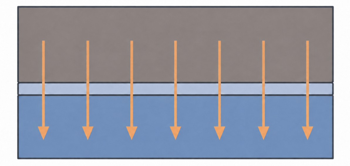
TIMs address this by filling the microscopic air gaps between cell surfaces and cooling structures — air being a poor thermal conductor compared to almost any solid or semi-solid interface material. A well-selected TIM keeps contact resistance low and consistent across the entire pack, not just under lab conditions but after years of thermal cycling and, for ESS, outdoor temperature swings.
Top 5 TIM Types Compared
Thermal Pads
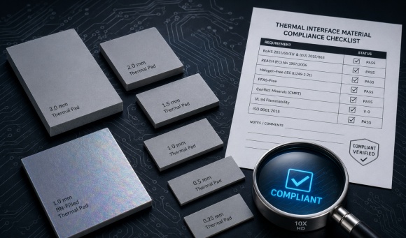
Thermal pads are pre-formed, compressible silicone or silicone-free sheets that sit between the cell (or module housing) and the cooling plate. Because they come in fixed thicknesses, they're straightforward to specify and easy to automate in high-volume assembly.
Typical thermal conductivity for standard silicone pads used in battery applications falls in the 1–6 W/m·K range, with higher-filler-loading variants reaching higher. Pads also provide inherent electrical isolation, which matters in high-voltage pack designs where creepage and clearance distances are tightly controlled.
The trade-off is that pad thickness itself adds thermal resistance — a thicker pad compensates for surface unevenness but also lengthens the heat path. Getting the compression ratio right (typically pads are designed to compress 10-30% under assembly pressure) is part of the selection process, not an afterthought.
Thermal Gap Fillers / Gels
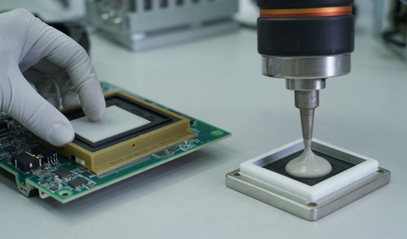
Gap fillers are semi-fluid, dispensable materials that conform to surface irregularities before curing or settling into a soft solid. They're particularly suited to large, uneven contact areas — a common scenario in prismatic and pouch cell module designs where cell-to-cell dimensional tolerance stacks up across a pack.
Because gap fillers flow into place rather than requiring precise pre-cut dimensions, they tolerate assembly variation better than pads in large-format packs. The trade-off is process control: dispensing volume, bead pattern, and cure time all need to be validated for consistent bond line thickness across a production line, which is a different manufacturing discipline than placing a pre-cut pad.
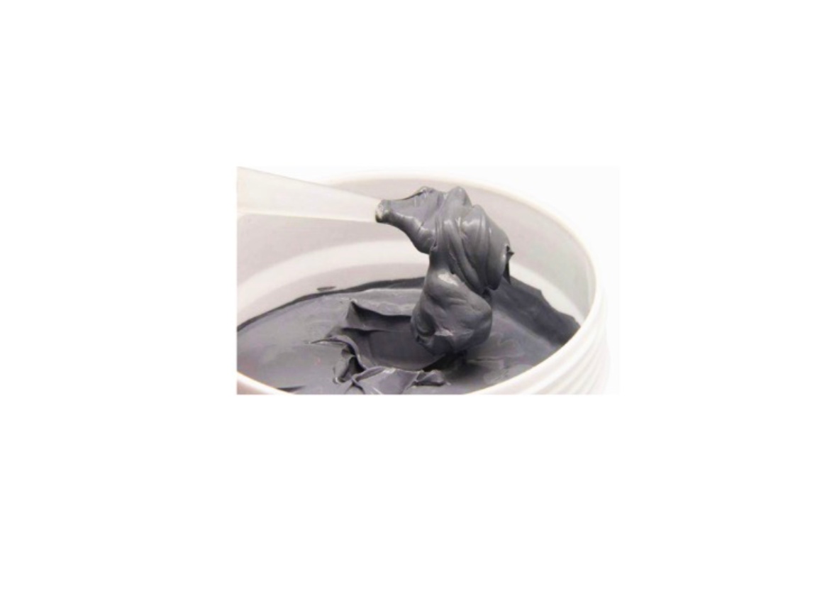
Thermal Grease / Paste
Thermal greases achieve very thin bond lines and correspondingly low thermal resistance, since there's no solid pad thickness limiting how close the two surfaces can sit. This makes grease attractive where minimizing thermal resistance is the top priority.
The known limitation in battery applications is long-term stability. Grease is prone to pump-out — gradual migration away from the contact area — and dry-out under repeated thermal cycling, both of which raise thermal resistance over the pack's service life. For this reason, grease sees more use in prototype and short-lifecycle battery designs than in production EV or ESS packs rated for a decade or more of service.
Phase Change Materials (PCM)
PCMs are solid at room temperature — easy to handle and place like a pad — but transition to a soft, conformable state around the battery's typical operating temperature, usually in a phase change range around 45-60°C depending on formulation. Once softened, the material flows into surface irregularities much like a grease, then behaves like a stable solid again once temperatures drop.
This combination — solid for handling and assembly, conformable in operation — is why PCMs are increasingly specified in ESS and EV applications with frequent charge-discharge cycling: they combine low initial contact resistance with better long-term stability than grease, without the pump-out concern.
Graphite Sheets / Films
Graphite films are thin, lightweight, and provide high in-plane thermal conductivity — spreading heat laterally across a surface rather than conducting it through the material's thickness the way pads and gap fillers do. In-plane conductivity for battery-grade graphite films typically ranges from roughly 400 up to 1,500+ W/m·K, depending on grade, though through-plane conductivity is much lower.
This makes graphite films most useful as a heat-spreading layer — reducing hot spots across a cell or module surface — rather than as the primary thermal path to a cooling plate. In battery pack design, graphite is often paired with a second TIM (a pad or gap filler) that handles the through-plane path to the cooling structure.

Quick Comparison
| TIM Type | Typical Thermal Conductivity | Electrical Insulation | Rework/Reuse | Best Suited For |
|---|---|---|---|---|
| Thermal Pads | 1-6 W/m·K | Yes | Moderate | High-volume automated assembly, uniform gaps |
| Gap Fillers / Gels | 1-5 W/m·K | Usually yes | Low (dispensed) | Large-area, uneven surfaces (prismatic/pouch packs) |
| Thermal Grease | 3-8 W/m·K | Varies by formulation | Low | Prototypes, short-lifecycle designs |
| PCM | 1-5 W/m·K | Usually yes | Low once phase-changed | Cyclic loads, long-term reliability priority |
| Graphite Sheets | 400-1,500+ W/m·K (in-plane) | No (often needs pairing) | High | Heat spreading, space-constrained modules |
Values reflect general industry ranges and vary by specific product formulation — always confirm against a supplier's tested datasheet for the exact grade under consideration.
Key Selection Criteria for EV & ESS Battery Pack Design
Choosing among these five categories comes down to a handful of trade-offs that recur across most battery pack projects:
Thermal conductivity vs. mechanical compliance. The highest-conductivity option isn't always the right one — a stiff, highly-filled material that doesn't conform well to real-world surface tolerances can end up with worse actual contact resistance than a lower-conductivity material that fills gaps completely.
Electrical insulation requirements. In high-voltage packs, insulation resistance and dielectric breakdown voltage matter as much as thermal performance — graphite's electrical conductivity, for example, is exactly why it's typically paired with an insulating layer rather than used alone against a live cell surface.
Reliability under vibration and thermal cycling. EV packs see continuous vibration; ESS packs see years of daily thermal cycling. A material that performs well in a single lab test but pumps out, cracks, or delaminates after a few hundred cycles isn't a viable production choice, regardless of its initial conductivity numbers.
Assembly and manufacturability. Pads suit automated pick-and-place lines; gap fillers require dispensing equipment and cure-time management; PCMs need placement care since they're less forgiving of misalignment once heated. The "best" material on paper can still be the wrong choice if it doesn't fit the production line it needs to run on.
Cost-performance balance. Thermal performance requirements should be set by the actual thermal budget of the pack design — over-specifying conductivity beyond what the cooling system can use elsewhere in the thermal path adds cost without a corresponding safety or performance benefit.
Application Scenarios: EV Battery Packs
Cell format drives a lot of the TIM decision in EV packs. Prismatic cells have flat, rigid surfaces that pair well with pre-cut pads — dimensional consistency makes pad placement predictable across a production line. Pouch cells, by contrast, can bulge slightly during charge cycles, and that dimensional change over the pack's life makes a compressible gap filler or a compliant pad a safer choice than a rigid interface. Cylindrical cell packs introduce a different challenge again: the contact area between round cells and a flat cooling plate is inherently limited, which is why many cylindrical designs rely on potting compounds or gap fillers that can flow around the cell geometry rather than a flat pad that only contacts a fraction of the surface.
Beyond the cell-to-cooling-plate interface, EV packs also need thermal management at the module-to-module and module-to-enclosure level, where graphite films are often used to spread heat away from localized hot cells before it reaches the primary cooling path. Vibration resistance is a constant requirement across all of these interfaces — a TIM that performs well in static lab testing but loosens or migrates under sustained road vibration will show degraded performance well before the vehicle reaches its design mileage.
Application Scenarios: Energy Storage Systems (ESS)
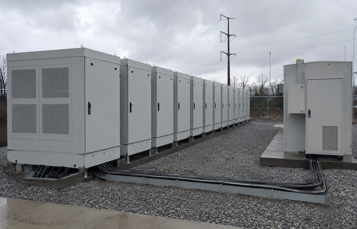
ESS installations present a different set of constraints. Unlike an EV pack that operates in a relatively controlled cabin or underbody environment, stationary ESS units — particularly outdoor and utility-scale installations — see wider ambient temperature swings across seasons, along with humidity and, in some cases, direct sun exposure on the enclosure. This makes long-term material stability a higher priority than in many EV applications, since ESS packs are typically rated for service lives measured in over a decade rather than the vehicle's typical ownership cycle.
This is also where phase change materials tend to see stronger consideration in ESS design — the repeated daily charge-discharge cycling common in grid-support and peak-shaving applications benefits from a TIM that maintains conformability over thousands of cycles without the pump-out risk associated with grease.
It's also worth noting that thermal management needs in an ESS installation extend beyond the battery cells themselves — the power conversion system (PCS) and inverter components that sit alongside the battery racks generate their own significant heat load, and TIM selection for those power electronics follows a related but distinct set of criteria around dielectric strength and high-power thermal cycling.
Common Mistakes in TIM Selection
A few recurring missteps show up across battery pack projects, regardless of application:
Optimizing for thermal conductivity alone. A datasheet's headline W/m·K number is one input among several — mechanical compliance, assembly tolerance, and long-term stability under the pack's actual duty cycle often matter more to real-world thermal resistance than the conductivity spec by itself.
Underestimating aging and pump-out risk. Materials that perform well in initial qualification testing can degrade meaningfully over a pack's service life, particularly greases and lower-quality gap fillers under sustained thermal cycling. Qualification testing should include cycling that reflects the actual expected service life, not just an initial performance check.
Treating manufacturability as a downstream concern. A TIM that works in a hand-built prototype can create real bottlenecks once a design moves to automated, high-volume production — dispensing consistency, cure time, and placement tolerance all need to be validated against the actual production line, not just a lab bench setup.
How to Qualify a TIM Supplier for Battery Projects
Beyond the material itself, supplier qualification is where many battery pack projects run into avoidable delays. A few areas worth confirming early in the sourcing process: consistent batch-to-batch material properties (variation in filler distribution can shift thermal conductivity between lots), documented testing under conditions that match the pack's actual thermal and mechanical duty cycle rather than only standard lab conditions, and the supplier's ability to support custom die-cutting or dispensing formats specific to the pack geometry. For a more detailed framework on evaluating TIM suppliers before committing to a production volume, see our [guide on validating a TIM supplier].
FAQ
Q1. What is the best TIM for EV batteries?
There's no single best option across all EV designs. Gap fillers and phase change materials are widely used for their ability to handle large contact areas and withstand repeated cycling, while thermal pads remain the standard choice where dimensional consistency and high-volume automation are the priority.
Q2. Can one TIM type fit all battery applications?
No. Cell format (prismatic, pouch, or cylindrical), production volume, and the pack's expected service environment all shift the trade-offs differently — a material well suited to a cylindrical ESS rack may not be the right fit for a pouch-cell EV module.
Q3. How does TIM selection affect battery safety?
By maintaining consistent, low thermal resistance across the pack, a well-selected TIM reduces the likelihood of localized hot spots and uneven cell aging — both of which are contributing factors in thermal runaway scenarios.
Q4. Are TIMs reusable or reworkable during battery pack assembly?
Generally, gap fillers and greases are single-use once dispensed and cured. Thermal pads and certain phase change sheet formats offer more flexibility for rework during prototyping or low-volume assembly, though this becomes less relevant once a design moves to production volumes.
Conclusion
Selecting a thermal interface material for an EV or ESS battery pack isn't a matter of finding the highest conductivity number on a datasheet — it's a matter of matching material properties to the pack's specific cell format, production process, and service life requirements. Pads offer consistency and easy automation; gap fillers handle large, uneven surfaces; PCMs balance initial performance with long-term cycling stability; grease trades long-term reliability for minimal bond line thickness; and graphite films solve heat-spreading problems that the other four don't directly address.
The right approach is usually to narrow down candidates based on the pack's actual thermal budget and mechanical constraints, then validate with cycling tests that reflect real service conditions before committing to a production volume — rather than selecting based on a single conductivity spec in isolation.