Welcome to Taxo Tape
Thermal Interface Materials for Battery Packs: Selection Criteria for Long-Term Reliability

Introduction
TIM selection for battery packs follows different rules than TIM selection for most other power electronics applications. The thermal interface between a power component and a heatsink in an inverter or LED driver is essentially static — the gap is fixed at assembly and stays fixed. In a battery pack, the interface is not static. Cells expand and contract with every charge and discharge cycle, the pack operates for 10 years or more in demanding environments, and a TIM failure does not just raise component temperature — it accelerates cell aging non-uniformly across the pack, which compounds into capacity fade and safety risk over time.
Three factors make battery pack TIM selection distinctly more demanding than standard power electronics:
Thermal cycling occurs continuously and at a different frequency and profile than in most inverter or power supply applications. A passenger EV charged daily accumulates hundreds of cycles per year; a grid storage system may cycle multiple times per day. The TIM must maintain its interface characteristics across thousands of these cycles without meaningful degradation.
Mechanical swelling is a variable that simply does not exist at most other TIM interfaces. Lithium-ion cells — particularly prismatic and pouch format cells — expand physically during charging and contract during discharge. The TIM must accommodate this dimensional change without losing contact or generating stress concentrations that damage the cell or the cooling structure.
Service life targets in battery applications are long and the consequences of early failure are significant. A traction battery pack warranted for 8 years or 160,000 kilometers cannot have a TIM specification that degrades noticeably before that point. Selecting a TIM based on initial assembly performance without evaluating long-term behavior is a specification error that will surface in the field.
This guide covers TIM selection for battery pack applications — cell-to-cooling plate interfaces, BMS board component interfaces, and module assembly bonding — with specific attention to the mechanical and long-term reliability requirements that differentiate this application from standard power electronics. It is written for design engineers and procurement managers working on EV battery packs, industrial energy storage systems, and UPS battery modules.
The Thermal Challenge in Battery Pack Design
Heat generation during charge and discharge
Lithium-ion cells generate heat through two primary mechanisms. Ohmic heating — resistive losses in the cell's internal resistance — scales with the square of current and dominates at high charge and discharge rates. Electrochemical reaction heat from the charge and discharge reactions contributes additional thermal load that varies with state of charge and cell chemistry.
In a high-rate EV discharge scenario, a large-format prismatic cell may dissipate 5–15W continuously, with peak values during acceleration events considerably higher. Across a pack of hundreds of cells, the total thermal management requirement is substantial. The TIM at the cell-to-cooling plate interface is the primary thermal pathway for extracting this heat from each individual cell.
Why uniform temperature distribution matters
Battery cells are sensitive to temperature in two ways. First, electrochemical performance — capacity, internal resistance, charge acceptance — degrades at both high and low temperatures. Second, and more critical for long-term pack health, cells age faster at elevated temperatures following Arrhenius kinetics similar to the electrolytic capacitor relationship in power electronics. A cell running 10°C hotter than its neighbors ages proportionally faster, loses capacity sooner, and eventually becomes the weak link that limits the entire pack's usable energy.
Non-uniform TIM quality across a pack — whether from inconsistent dispensing, thickness variation, or localized degradation — produces non-uniform cell temperatures, which produces non-uniform aging, which produces cell imbalance. The battery management system compensates for imbalance to a point, but the underlying thermal root cause remains. This is why TIM consistency across the full pack is as important as the average thermal performance.
The thermal path
Heat flows from the cell's electrochemical core through the cell casing or surface, across the TIM layer, into the cooling plate, and from there to the coolant circuit. In liquid-cooled pack designs — the dominant architecture in EV traction batteries — the cooling plate is an aluminum structure with internal coolant channels maintained at a controlled temperature by the vehicle's thermal management system.
The TIM sits between the cell surface and the cooling plate. Its thermal resistance determines how large the temperature differential is between the cell surface and the coolant, which in turn determines the cell's steady-state operating temperature at a given heat generation rate. A TIM with twice the thermal resistance produces twice the temperature rise across the interface for the same heat flux — directly raising cell operating temperature and accelerating aging.
Cell swelling as a unique mechanical variable
Prismatic and pouch lithium-ion cells expand during charging as lithium ions intercalate into the anode material. The dimensional change is real and measurable — prismatic cells may expand 1–3% in thickness across their state of charge range, with additional irreversible swelling accumulating over the cell's lifetime as the electrode materials gradually degrade.
This expansion places cyclic compressive load on the TIM at the cell-to-cooling plate interface. A TIM that cannot accommodate this dimensional change — either because it is too rigid to compress further or because it loses contact as the cell contracts during discharge — will develop inconsistent contact over time. The result is increasing and non-uniform thermal resistance as the pack ages.
Why initial assembly performance is not enough
A TIM that measures excellent thermal resistance at initial assembly and passes short-term qualification testing can still fail the long-term reliability requirement if its mechanical and thermal properties degrade under the combined stress of thermal cycling and cell swelling. The degradation is gradual and may not be detectable until the pack has accumulated significant operational history — at which point the cells it was supposed to protect have already experienced elevated temperature exposure for an extended period.
TIM Types Used in Battery Pack Applications
Thermal gap fillers (1K and 2K dispensed)
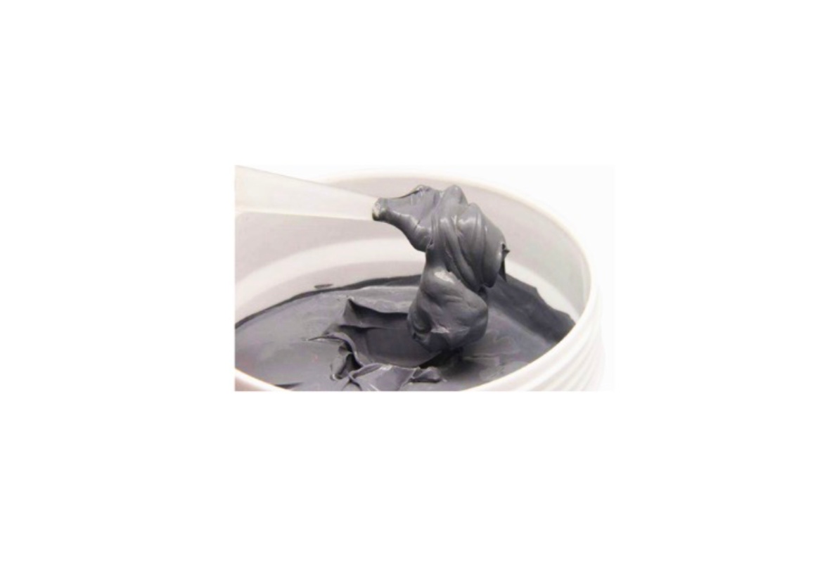
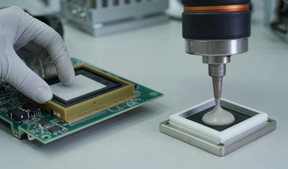
Dispensed gap fillers are the dominant TIM choice at cell-to-cooling plate interfaces in EV traction battery packs. Their advantages in this application are substantial: they conform completely to the cell surface and cooling plate geometry regardless of surface finish or flatness variation, they can be dispensed in precise patterns that match the cell layout, and their softness allows them to accommodate cell swelling without generating excessive back-pressure on the cell casing.
1K (single-component) gap fillers cure at room temperature or with mild heat and are well suited to automated dispensing on high-volume battery assembly lines. 2K (two-component) versions require mixing but offer faster cure cycles and access to higher conductivity formulations. Conductivity in commercial gap fillers for battery applications typically ranges from 2.0 to 6.0 W/m·K, with higher values available in premium formulations using BN or hybrid fillers.
The trade-off is process complexity relative to pads. Dispensing requires equipment, process control, and consistent material mixing and application to achieve uniform bond line thickness across the pack. Inconsistent dispensing is a production quality risk that pad-based solutions avoid.
Thermal pads
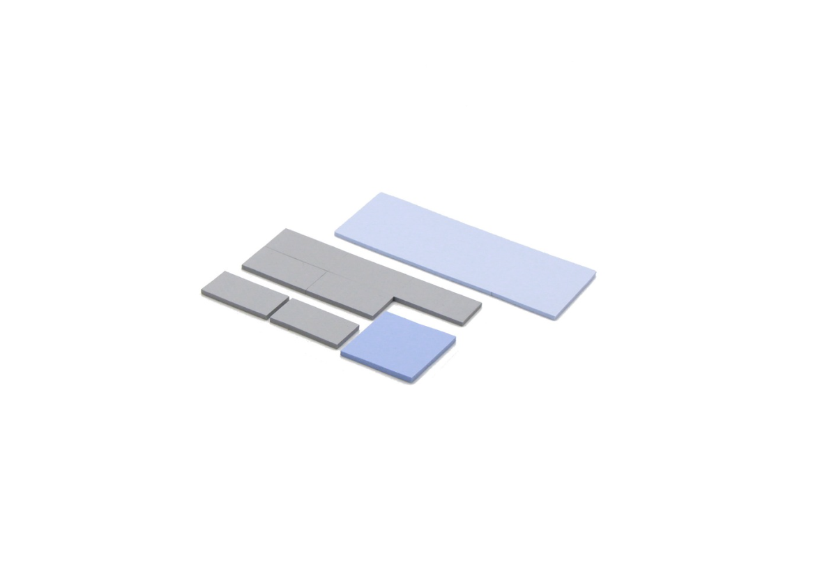
Pads are less common at cell-to-cooling plate interfaces in large-format EV packs, primarily because gap fillers handle surface variation and swelling accommodation more effectively at that interface. Pads are widely used elsewhere in battery systems — at power component interfaces on BMS boards, between power contactors and their mounting surfaces, and at interfaces within the battery junction box.
For BMS board power components — switching devices, current sensors, DC-DC converters — silicone thermal pads in the 3.0 – 6.0 W/m·K range are the standard choice, following the same selection logic as general power electronics applications.
Thermally conductive adhesive tapes
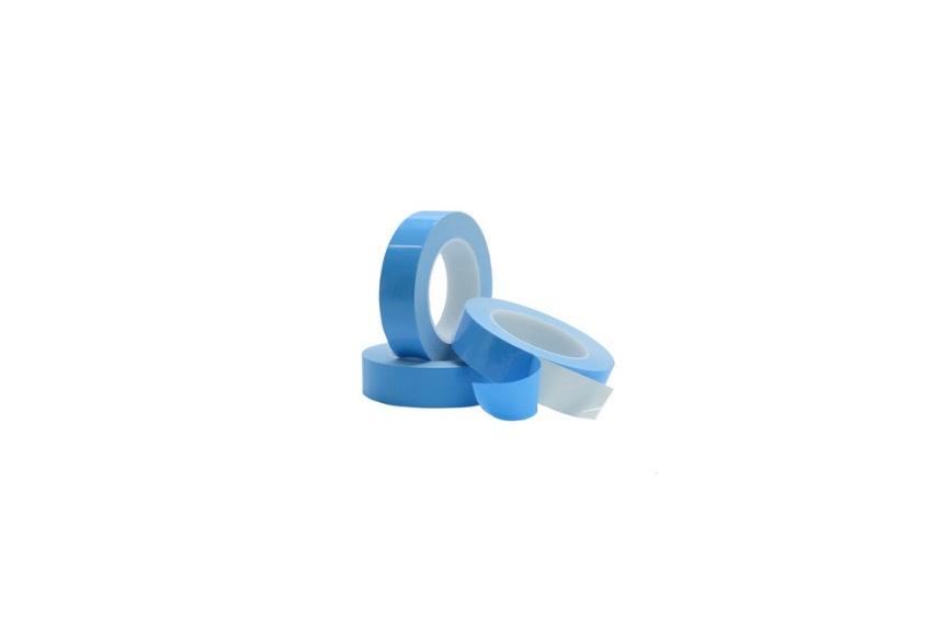
Adhesive tapes serve a structural bonding function in battery module assembly — bonding cell groups to module frames, attaching bus bar insulators, or securing components where mechanical fasteners are not practical. In these roles, the thermal conductivity of the tape is secondary to its adhesive strength, temperature resistance, and compatibility with the cell casing material.
The critical consideration with adhesive TIMs in battery applications is end-of-life reworkability. Cells bonded with aggressive adhesive tapes are difficult or impossible to separate without damage, which complicates battery recycling and second-life applications. Regulatory pressure on battery recyclability is increasing in both European and Asian markets, and this is pushing some pack designers toward non-bonding gap fillers at cell interfaces even where adhesive tapes would otherwise be technically suitable.
Phase change materials
PCMs are used in some high-performance battery designs where the thermal budget is tight and the assembly process can accommodate the handling requirements. Their cycling resistance is generally good, and their ability to conform fully at operating temperature makes them effective at interfaces with surface variation. In high-volume EV battery production, the process complexity of PCM application limits their adoption compared to dispensed gap fillers.
Thermal grease
Grease is largely avoided at cell-to-cooling plate interfaces in battery packs. The pump-out mechanism that causes problems in inverter applications is amplified in battery packs by the cyclic mechanical loading from cell swelling — each expansion and contraction cycle provides additional driving force for grease displacement. A grease-based interface in a non-serviceable sealed battery pack that cannot be re-greased is a known long-term reliability risk that most pack designers avoid by specification.
Comparison table
| TIM Type | Interface Location | Conductivity Range | Swelling Accommodation | Reworkable | Key Trade-off |
|---|---|---|---|---|---|
| Gap filler (1K/2K) | Cell-to-cooling plate | 2.0 – 6.0 W/m·K | Excellent | Yes | Process complexity |
| Thermal pad | BMS boards, power electronics | 3.0 – 8.0 W/m·K | Moderate | Yes | Less conformable than gap filler |
| Adhesive tape | Module bonding, structural | 0.8 – 3.0 W/m·K | Low | No | Recyclability concern |
| Phase change material | Precision interfaces | 3.0 – 7.0 W/m·K | Good | Yes | Assembly process requirement |
| Thermal grease | Not recommended for sealed packs | 3.0 – 8.0 W/m·K | Poor | N/A | Pump-out under cell swelling |
Key Selection Criteria Specific to Battery Applications
Thermal conductivity
Requirements differ significantly by interface location. At cell-to-cooling plate interfaces in EV traction packs, conductivity in the 2.0 – 4.0 W/m·K range covers most standard cell formats and cooling plate designs. Higher values — 4.0 – 6.0 W/m·K — are warranted in high-rate discharge applications where heat flux is elevated, such as performance EV platforms or fast-charging systems. At BMS board power component interfaces, the same 3.0 – 6.0 W/m·K range applicable to general power electronics applies.
The gap filler bond line thickness at cell interfaces is typically 0.3 – 1.0mm, which means even moderate conductivity values produce low absolute thermal resistance across that thin layer. In many standard EV pack designs, the cooling plate design and coolant temperature are the dominant factors in cell temperature, and TIM conductivity improvements above 3.0 – 4.0 W/m·K produce diminishing returns.
CTE compatibility
Coefficient of thermal expansion mismatch between the TIM and the adjacent materials — aluminum cooling plates, steel or aluminum cell casings — generates shear stress at the interface during thermal cycling. Over thousands of cycles, accumulated shear stress can cause delamination or cohesive failure within the TIM layer, particularly in stiffer formulations that cannot relieve stress through elastic deformation.
Soft, low-modulus gap fillers accommodate CTE mismatch through elastic compliance — they deform rather than transmit stress to the interface. Harder TIM formulations with higher elastic modulus are more susceptible to CTE-driven fatigue. For battery applications with wide operating temperature ranges and high cycle counts, low modulus is a selection criterion alongside thermal conductivity.
Compression and swelling accommodation
The TIM specification must account for the full range of cell thickness across the state of charge range plus the irreversible swelling that accumulates over the pack's service life. A prismatic cell expanding 2% in thickness over its SOC range and an additional 3% irreversibly over its service life requires the TIM to accommodate 5% total thickness increase while maintaining adequate contact at the cooling plate interface.
Gap fillers with low compressive modulus handle this most naturally — the material compresses as the cell expands and recovers as it contracts, maintaining contact throughout the cycle without generating excessive back-pressure. Specify the compressive stress vs. strain curve from the supplier and verify that the expected cell expansion falls within the elastic range of the material at the expected contact pressure.
Electrical insulation
The cooling plate in a liquid-cooled battery pack is typically grounded to the vehicle chassis or system ground. Cell casings in prismatic and cylindrical formats are electrically connected to one terminal of the cell. The TIM at the cell-to-cooling plate interface must provide electrical isolation between these two surfaces across the full operating voltage range of the pack.
Volume resistivity requirements vary by pack voltage, but a minimum of 10¹² Ω·cm is a common starting point for EV traction applications. Dielectric breakdown voltage should be verified against the pack's maximum operating voltage with adequate margin. Standard alumina and BN-filled gap fillers and pads are electrically insulating and meet these requirements in most applications — confirm the specific values against your isolation specification.
Flame retardancy
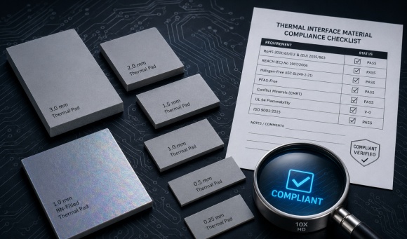
Battery packs are subject to thermal runaway risk, and the TIM materials inside the pack must not contribute to flame propagation if a cell event occurs. UL 94V-0 is the standard flame retardancy classification required in most EV and industrial battery pack material specifications. Verify that any TIM under consideration carries a UL 94V-0 rating and request the supporting test documentation — do not rely on general claims of flame retardancy without the certification data.
Reworkability and end-of-life considerations
Non-bonding gap fillers and pads allow cells to be separated from cooling plates without damage, which supports both in-process rework and end-of-life battery disassembly for recycling or second-life applications. Adhesive TIMs that permanently bond cells to the cooling structure complicate or prevent non-destructive disassembly.
European battery regulations under the EU Battery Regulation increasingly require design for disassembly and recyclability. For pack designs targeting European markets, specifying non-bonding TIMs at cell interfaces is becoming a compliance consideration alongside a technical one. Confirm the regulatory requirements for your target markets before defaulting to adhesive solutions for process convenience.
Long-Term Degradation Mechanisms in Battery TIMs
Battery TIMs face the same underlying thermal cycling degradation mechanisms that affect thermal interface materials across power electronics generally — for a broader look at these mechanisms, see Selecting TIMs for Long-Term Reliability Under Thermal Cycling. What follows here focuses on the additional complexity cell swelling introduces on top of that baseline.
Thermal cycling fatigue
Every charge and discharge cycle subjects the TIM interface to a mechanical loading and unloading event driven by cell expansion and contraction. The amplitude of this cyclic loading depends on cell format — pouch and prismatic cells swell more than cylindrical cells — and on the discharge rate, which affects how quickly and how much the cell heats up during operation.
Over thousands of cycles, this repeated mechanical stress accumulates damage in the TIM layer through two mechanisms. In stiffer materials, cyclic shear stress from CTE mismatch between the cell casing and cooling plate causes progressive cohesive cracking within the TIM. In softer materials, the repeated compression and recovery gradually alters the material's elastic properties — it becomes either permanently compressed or locally displaced — producing thickness non-uniformity across the interface.
Neither failure mode is visible during routine inspection. Both produce the same output: gradually increasing and non-uniform thermal resistance across the cell-to-cooling plate interface.
Compression set under sustained cell swelling pressure
Beyond the cyclic component, lithium-ion cells accumulate irreversible swelling over their service life as electrode materials expand permanently with repeated cycling. This means the TIM operates under a sustained background compressive load that increases over time, not just a cyclic load that returns to zero.
A gap filler or pad under sustained compression at elevated temperature will exhibit compression set — permanent thickness reduction that does not recover when the load is removed. For a TIM specified at 0.5mm initial thickness, 15% compression set means the material is permanently 0.075mm thinner after extended service. This changes the contact geometry at the interface and can open gaps at the edges of the cell footprint where swelling-induced curvature causes the cell surface to bow away from the cooling plate.
Request compression set data from suppliers at both the expected operating temperature and the maximum rated temperature, under a compressive load representative of your assembly clamping plus worst-case cell swelling pressure. This data should be available for any TIM seriously considered for battery applications.
Dry-out and hardening in dispensed gap fillers
Dispensed gap fillers — particularly silicone-based 1K and 2K formulations — can undergo gradual changes in mechanical properties over years of operation at elevated temperature. The silicone polymer matrix may experience partial cross-link density changes that increase stiffness over time, reducing the material's ability to accommodate cell swelling through elastic deformation. In some formulations, low-molecular-weight components volatilize slowly at operating temperature, reducing the material's volume and leaving a harder, less compliant residue.
The practical consequence is a gap filler that was soft and accommodating at initial assembly becoming progressively stiffer and less effective at the cell interface over the pack's service life. This degradation mode is particularly relevant for packs operating at elevated continuous temperatures — fast-charging applications, high-ambient deployments — where the thermal driving force for polymer aging is higher.
How degraded TIM increases cell temperature non-uniformity
TIM degradation is rarely uniform across a battery pack. Local variations in initial dispensing thickness, cell surface flatness, clamping pressure, and cell-to-cell swelling differences mean that some interfaces degrade faster than others. The result is a growing spread in cell temperatures across the pack over time.
A cell running 5°C hotter than its neighbors due to a locally degraded TIM interface ages noticeably faster following Arrhenius kinetics. Its capacity fades sooner, its internal resistance increases more quickly, and it becomes the cell that limits the pack's usable energy. The BMS compensates by limiting charge and discharge to protect the weakest cell, reducing effective pack capacity for all users. The thermal root cause — localized TIM degradation — is difficult to detect without disassembly and thermal mapping.
What accelerated aging test data from suppliers should show
When evaluating a TIM for a battery application, request the following from the supplier before making a production decision:
Thermal cycling test results: thermal resistance measured before and after a defined number of cycles (minimum 500, ideally 1000+) across a temperature range representative of your operating profile. The acceptable degradation threshold depends on your thermal budget, but a thermal resistance increase of less than 10% after 1000 cycles is a reasonable benchmark for a well-performing battery TIM.
Compression set data: measured at operating temperature and maximum rated temperature under representative compressive load, reported as percentage of original thickness after a defined time period (typically 22 or 70 hours per ASTM D395, with longer-term data preferred for battery applications).
Aged mechanical properties: hardness or modulus measured after extended thermal aging (1000 hours at maximum rated temperature is a common accelerated aging protocol), confirming that the material remains adequately soft and compliant after the equivalent of years of service.
Suppliers who cannot provide this data for a product being positioned for battery applications should be approached with caution. The data exists for well-characterized materials; its absence usually indicates insufficient application-specific testing.
Application-Specific Recommendations
EV traction battery packs
The cell-to-cooling plate interface is the primary TIM application in traction packs, and dispensed gap filler is the appropriate material type for this interface in the large majority of designs. Conductivity in the 2.0 – 4.0 W/m·K range is sufficient for standard passenger EV duty cycles; high-performance platforms with aggressive discharge rates or fast-charging capability should evaluate 4.0 – 6.0 W/m·K formulations.
Key specification requirements beyond conductivity: UL 94V-0 flame retardancy, volume resistivity above 10¹² Ω·cm, compression set below 15% after 70 hours at maximum operating temperature, and documented thermal cycling stability over 500+ cycles. Non-bonding formulation strongly preferred to support end-of-life disassembly.
For module assembly bonding where structural adhesion is required, thermally conductive adhesive tape or structural adhesive with moderate thermal conductivity is appropriate — but verify recyclability requirements for your target markets before committing to a permanently bonded design.
Industrial energy storage systems (ESS)
Grid-scale and commercial ESS installations use larger-format prismatic or pouch cells with different cycling profiles than automotive applications. Daily cycling in grid storage may be lower in peak rate than automotive but higher in total cycle count over the system's 15–20 year design life.
The extended service life target makes long-term TIM stability even more critical than in automotive applications. Specify gap fillers with documented aging data at operating temperature over 2000+ hours. The lower peak discharge rates in most ESS applications reduce the instantaneous heat flux at the cell interface, which means moderate conductivity (2.0 – 3.0 W/m·K) is often sufficient — the focus shifts toward long-term mechanical stability over peak thermal performance.
Serviceable designs are more common in ESS than in automotive packs, which changes the TIM specification calculus. If the cooling plate can be separated from the cell stack for maintenance, reworkability is less critical and some adhesive-bonded designs become acceptable.
UPS battery modules
UPS battery systems operate at moderate cycling rates — typically one full cycle per day or less in standby UPS applications — but may have long shelf periods where the battery sits at partial state of charge. Thermal management requirements are less demanding than EV traction applications, and the dominant TIM requirement shifts toward long-term chemical stability during storage rather than high-rate cycling resistance.
Standard silicone thermal pads in the 3.0 – 5.0 W/m·K range are appropriate for power component interfaces in UPS battery modules. For cell-to-cooling interfaces in larger UPS battery systems, moderate-conductivity gap fillers (2.0 – 3.0 W/m·K) are adequate given the lower heat flux. Many UPS designs use air cooling rather than liquid cooling, which reduces the TIM specification requirements further — the limiting thermal resistance in air-cooled designs is usually the heatsink-to-air interface, not the TIM.
BMS power electronics
The battery management system board contains power components — MOSFETs for cell balancing, current measurement shunts, DC-DC converters, communication interfaces — that require thermal management independent of the cell interfaces. These components dissipate modest power relative to the cells themselves but operate continuously and must remain within their rated temperature range across the full battery operating environment.
Silicone thermal pads in the 3.0 – 6.0 W/m·K range are the standard choice for BMS power component interfaces, following the same selection logic as general power electronics. The BMS board is typically mounted inside the battery pack enclosure and does not require special TIM considerations beyond those applicable to standard industrial electronics — except that UL 94V-0 flame retardancy applies to TIM materials used anywhere inside the pack enclosure.
Common Selection Mistakes in Battery Pack TIM Specification
Specifying conductivity without checking CTE compatibility
Conductivity is the first number engineers look at, but in battery applications it is not the most critical long-term parameter. A high-conductivity TIM with a high elastic modulus that cannot accommodate CTE mismatch under thermal cycling will develop interface cracks and delamination over time, degrading thermal performance despite its initial conductivity advantage. Always check modulus and CTE alongside conductivity when evaluating battery TIM candidates.
Using bonding adhesive TIMs where battery recycling is required
Permanently bonded cells are a recycling and second-life problem that is becoming a regulatory issue in addition to a technical one. Specifying adhesive TIMs at cell interfaces for process convenience without considering end-of-life requirements is a decision that may need to be reversed later at significant redesign cost. Evaluate recyclability requirements for your target markets at the material selection stage, not after the design is frozen.
Ignoring cell swelling when specifying pad thickness and hardness
Specifying pad thickness based on the nominal assembly gap without accounting for cell expansion leaves no mechanical margin for swelling accommodation. A pad compressed to its minimum recommended thickness at initial assembly will be over-compressed and potentially damaged at maximum cell swelling. Specify thickness with the full swelling range in mind, and verify that the selected hardness allows adequate compression without generating back-pressure that exceeds the cell casing's structural rating.
Selecting grease for sealed, non-serviceable battery modules
The combination of cyclic cell swelling and long service life requirements makes thermal grease a poor choice for sealed battery pack applications. Pump-out under cyclic mechanical loading is a known failure mode that will degrade the interface over time in a module that cannot be opened for re-greasing. This is not a theoretical risk — it is the same mechanism that causes grease failures in inverter applications, amplified by the additional mechanical driving force from cell swelling.
Skipping long-term cycling test validation before production approval
Initial assembly thermal resistance measurements tell you what the TIM does at day one. They tell you nothing about what it does after 2,000 cycles at operating temperature under cell swelling pressure. For a battery pack with a 10-year warranty, this gap in validation data is a significant risk. Run accelerated cycling tests on representative samples before approving a TIM for production — the time and cost invested in this step is small relative to the cost of a field reliability issue at scale.
Conclusion
Battery pack TIM selection is not a straightforward thermal conductivity comparison. The mechanical demands of cell swelling, the long service life targets, the flame retardancy and electrical isolation requirements, and the increasing regulatory pressure on battery recyclability all add selection criteria that do not appear in a standard power electronics TIM evaluation.
The material type decision — gap filler versus pad versus adhesive tape — is driven by interface geometry and mechanical requirements, not by conductivity alone. At cell-to-cooling plate interfaces, dispensed gap filler dominates for good reasons: conformability, swelling accommodation, and reworkability. At BMS component interfaces, standard silicone pads apply. Adhesive tapes have a role in module assembly but require careful evaluation against recycling requirements.
Long-term stability under thermal cycling and sustained compression is the parameter that separates adequate TIM specifications from reliable ones in battery applications. Validate through accelerated cycling tests with supplier-provided degradation data, not through initial assembly measurements alone. Compression set, aged modulus, and post-cycling thermal resistance are the numbers that matter for a 10-year pack.
If you are working through TIM selection for a battery pack application and need material recommendations or samples for evaluation, contact us with your cell format, cooling architecture, and operating profile.