Welcome to Taxo Tape
TIM Selection for EV Battery Modules: Materials & Design Guide
Introduction
The battery pack is the single most temperature-sensitive component in an electric vehicle, and it's also the one where a thermal interface material's job is least forgiving. During charge and discharge cycles, lithium-ion cells generate heat through internal resistance and electrochemical reactions — heat that scales up with current density and power demand, and accumulates faster in large modules or fast-charging systems than in almost any other power electronics application.
Left unmanaged, this heat doesn't distribute evenly. Cell-to-cell temperature variation as small as a few degrees can accelerate capacity fade unevenly across a pack, and in the more severe cases, contributes to the conditions that precede thermal runaway. The thermal interface material sitting between each cell and the cooling structure is what determines whether that heat actually reaches the cooling system efficiently or gets trapped at the interface — making TIM selection a far more consequential decision in EV battery design than its modest bill-of-materials cost would suggest.
How Heat Moves Through a Battery Module
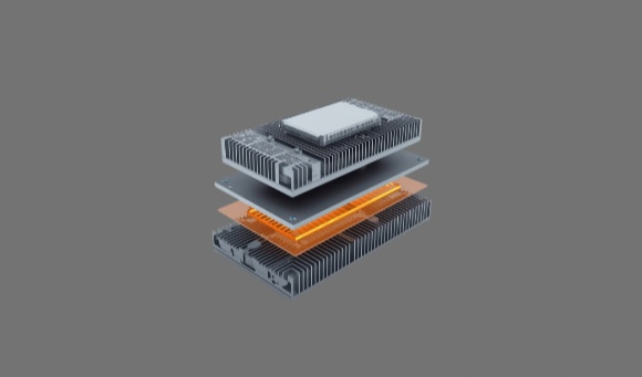
The heat flow path in a typical battery module starts at the cell surface, passes through the thermal interface layer, continues into the cooling plate, and finally dissipates into the vehicle housing or coolant circuit. Understanding this path — and where it bottlenecks — is the starting point for any TIM specification decision.
Two cooling architectures dominate current EV battery designs. Liquid-cooled systems, where coolant channels or cold plates make direct contact with the module base, deliver high heat-transfer efficiency and are the standard architecture for high-performance EV traction packs. Air-cooled systems are lighter and mechanically simpler but limited in the total heat load they can remove, making them more suitable for mild or hybrid vehicle applications with lower thermal demands.
Regardless of architecture, several recurring challenges limit heat transfer at the cell interface: contact resistance between the cell surface and the cooling structure, microscopic gaps created by uneven cell surfaces or normal manufacturing tolerances, and compact module geometries that leave little room for airflow or supplementary cooling structures. These are exactly the conditions a well-selected TIM is designed to compensate for.
Where TIMs Are Used in an EV Battery Pack
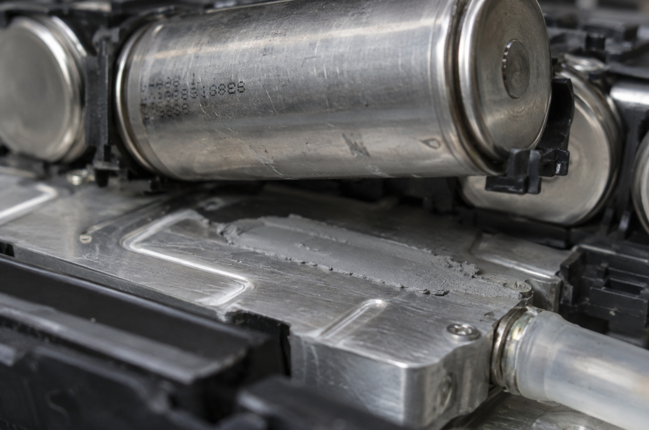
TIMs show up at several distinct interfaces within a battery pack, each with somewhat different requirements. Between cylindrical or prismatic cells and cooling plates, TIM provides the primary thermal path to a liquid-cooled base, and this interface typically sees the most demanding combination of thermal and mechanical requirements. Between busbars or BMS components and heat spreaders, TIM manages more localized, generally lower-magnitude heat generation from power electronics and monitoring circuitry. Between module frames and casings, TIM supports secondary conduction cooling paths where the primary cell-level cooling needs supplementing.
Maintaining consistent contact pressure across hundreds or thousands of cells is one of the harder practical challenges in EV battery assembly — a well-selected TIM compensates for uneven surfaces and normal assembly tolerances so that every cell contributes evenly to the pack's overall thermal performance, rather than a handful of poorly-contacted cells running hotter and aging faster than the rest.
Key Material Properties to Evaluate
Selecting a TIM for an EV battery module means balancing several properties simultaneously, since optimizing for any one in isolation tends to compromise another.
Thermal conductivity in the 2–8 W/m·K range covers most EV battery applications without introducing excessive stiffness or cost — higher isn't automatically better if it comes at the expense of conformability. Compressibility matters as much as conductivity: a soft, conformable material maintains uniform pressure across the cell surface and prevents cell deformation, while maximizing real contact area and minimizing trapped air. Electrical insulation is a hard requirement in most designs, since battery modules commonly operate at hundreds of volts — the TIM needs sufficient dielectric strength to prevent short circuits while still conducting heat efficiently. Long-term stability under continuous thermal cycling, vibration, and humidity exposure determines whether the material's day-one performance holds up over the pack's service life — resistance to pump-out, drying, and compression set is essential here. Density and weight round out the list as automakers push to reduce overall vehicle mass; lower-density TIM formulations support that goal without necessarily sacrificing thermal or mechanical performance.
Comparing TIM Types for Battery Modules
Different battery designs favor different TIM types, and each comes with its own set of trade-offs worth weighing against your specific module architecture.
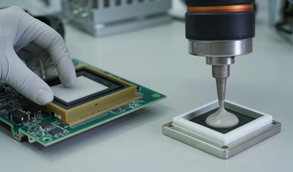
Thermal pads are soft, solid sheets — easy to handle, compress well, and provide reliable electrical insulation, making them well suited to consistent gap sizes and automated placement. Gap fillers are dispensable materials that self-level and conform to complex geometries, a better fit where gap size varies across the module or where automated dispensing is already part of the production process. Thermal grease delivers very low interface resistance and strong initial thermal efficiency, but its handling requirements and long-term stability concerns make it less practical for large-scale EV assembly compared to pad or gap filler formats. Phase change materials stay solid at room temperature and soften during operation, filling micro-voids for stable contact over time — a good fit for systems with frequent temperature fluctuations. Graphite sheets provide strong in-plane thermal spreading and are often paired with an insulating pad or film, common in hybrid designs where heat needs to be distributed laterally before reaching the primary cooling path.
No single property decides the right material — thermal conductivity alone doesn't determine which TIM actually performs best in a given module; mechanical compliance, insulation requirements, and manufacturability all factor into a workable specification.
Key Selection Criteria for Engineers
Choosing the right TIM for a battery module comes down to a sequence of practical checks, each narrowing the field further.
Define operational parameters first. Quantify power density, allowable temperature rise (ΔT), and the expected pressure range within the module before evaluating specific materials — these numbers set the minimum thermal performance the TIM actually needs to deliver, rather than defaulting to the highest-conductivity option available. Match thickness and softness to tolerance stack-up. Cell and cooling plate surfaces are rarely perfectly flat, so the TIM's compressibility and thickness tolerance need to accommodate that variation — too firm a material risks damaging cells under compression, while too soft a material can produce uneven contact across the interface. Evaluate dielectric performance rigorously. High-voltage EV systems demand robust insulation; confirm the material's dielectric breakdown strength and volume resistivity provide adequate margin against your pack's operating voltage, not just its nominal rating. Consider manufacturability alongside performance. In mass production, how easily a TIM integrates into automated assembly — placement consistency, reworkability, effect on yield — matters as much as its lab performance numbers. Validate before committing to production. Thermal resistance (Rth) testing and thermal cycling reliability testing under representative conditions confirm the material performs as expected over time, not just in initial characterization.
Design and Application Best Practices
Selecting a high-conductivity material is only part of a reliable thermal design — correct application matters just as much.
Ensure uniform contact across the pack. In a large EV module containing hundreds of cells, even small gaps or voids in TIM coverage create local hot spots that accelerate aging at exactly those cells, undermining pack-level performance even when the average TIM specification looks adequate on paper. Anticipate common failure modes during cycling. Pump-out, voiding, and oil bleed can degrade grease-based interfaces under repeated thermal cycling — specifying low-bleed formulations and validating stability under representative cycling conditions heads off these failures before they reach production. Integrate thoughtfully with structural materials. Some designs pair TIMs with adhesives, foams, or gaskets to add vibration damping and mechanical reinforcement alongside thermal performance — proper material pairing supports both functions without one compromising the other.
A concrete illustration of the stakes: in a 400V EV battery pack, replacing a 2.0 W/m·K pad with an optimized 3.0 W/m·K silicone-based pad reduced the maximum cell-to-cell temperature difference by 5°C — a change that improved both cycle life and charge consistency across the pack, from what looks like a modest conductivity upgrade on paper.
Emerging Trends in Battery TIM Solutions
Battery TIM formulations are shifting alongside broader trends in EV manufacturing and sustainability requirements. Non-silicone and low-volatile compounds are seeing growing adoption as safety and environmental regulations tighten, reducing volatile content and contamination risk within sealed battery enclosures. Recyclable and lightweight materials are gaining attention as automakers pursue circular-economy goals without sacrificing thermal performance — a consideration that increasingly intersects with end-of-life disassembly requirements for the pack as a whole. Automation-friendly formats — roll-form, die-cut, and pre-applied pad configurations — continue to gain ground, since they support faster automated placement and reduce assembly waste relative to manual dispensing methods.
How This Differs from General Power Electronics TIM Selection
TIM selection for an EV battery module isn't simply power electronics selection logic applied to a different component. The interface here is not static the way it typically is at an inverter or LED driver interface — cells physically expand and contract with every charge-discharge cycle, which means the TIM has to accommodate a mechanical variable that most power electronics interfaces never encounter. Service life expectations also run longer, often a decade or more, with correspondingly higher consequences if the material's long-term stability doesn't hold up. And the safety profile is different in kind, not just degree — a degraded interface here doesn't just risk a shortened component lifespan, it contributes to non-uniform cell aging that can compound into pack-level safety concerns over time.
For the broader picture of how TIMs function across EV, ESS, and industrial battery applications generally, see Thermal Interface Materials in Battery Thermal Management. For a deeper look specifically at the long-term degradation mechanisms — cell swelling accommodation, compression set under sustained pressure, CTE compatibility — that separate an adequate battery TIM specification from a reliable one, see Thermal Interface Materials for Battery Packs: Selection Criteria for Long-Term Reliability.
FAQ
Q: What thermal conductivity is recommended for EV battery applications?
For most EV modules, materials in the 2–5 W/m·K range offer a workable balance of thermal performance and compressibility. Higher-conductivity TIMs at 6 W/m·K or above may be warranted for high-power or fast-charging systems where heat flux at the cell interface is elevated, but confirm the added conductivity is actually needed against your specific thermal budget before defaulting to it.
Q: Can the same TIM be used for both module and pack level interfaces?
Not always. Module-level interfaces at the cell-to-cooling-plate boundary often benefit from softer, more conformable pads or gap fillers to accommodate cell swelling and surface variation, while pack-level structural interfaces tend to prioritize durability and mechanical integrity over maximum conformability. Selecting by interface location, rather than standardizing on one material across the pack, generally produces better outcomes.
Q: How do I verify TIM reliability under vibration and temperature cycling?
Combined thermal cycling, vibration, and accelerated aging testing — assessing pump-out resistance, mechanical stability, and thermal resistance consistency over the test duration — provides the clearest picture of long-term performance. Initial thermal resistance measurement alone doesn't capture how a material behaves after the cyclic mechanical loading a battery pack actually experiences in service.
Conclusion
A well-designed thermal interface is foundational to both safety and long-term reliability in EV battery packs, and getting it right means treating TIM selection as a system-level decision rather than a simple conductivity comparison. Balancing thermal performance against mechanical compliance, electrical isolation, and manufacturability — then validating that balance through cycling and aging tests rather than datasheet values alone — is what separates a specification that performs in the lab from one that holds up across a decade of real-world service.
For the wider context of TIM applications across battery thermal management generally, and for a closer look at the long-term reliability mechanisms specific to battery applications, see the related guides linked throughout this article.
Contact TaxoTape® to discuss TIM selection for your EV battery module design →