Welcome to Taxo Tape
How to Select TIMs for 5G Base Station Thermal Design
Introduction
5G networks have pushed power density in base station hardware to levels that earlier generations of telecom equipment never had to contend with. Small cells and high-frequency band deployments pack more processing power into smaller enclosures, which means RF amplifiers, transceivers, and power modules now generate more heat in less space than their 4G predecessors did.
This concentration of heat isn't just a component reliability concern — excessive junction temperatures degrade signal integrity and system stability alongside shortening component lifespan. The thermal interface material bridging each heat-generating device to its heat sink is what determines whether that heat actually reaches the cooling structure efficiently, making TIM selection a meaningfully consequential decision in 5G equipment design rather than a late-stage detail to fill in after the mechanical layout is finalized.
Why Compact 5G Designs Create Thermal Bottlenecks
The push toward compact, lightweight base station hardware — small cells, Remote Radio Units (RRUs) — has packed multiple high-power components into dense layouts with limited airflow and confined enclosures, leaving little margin for thermal inefficiency anywhere in the design.
Power density in modern small cell and RRU power amplifier modules commonly runs in the range of several watts per square centimeter at the device level — considerably higher than the more distributed heat loads typical of earlier, larger base station form factors. In these compact layouts, heat distribution across multilayer PCBs is often uneven, since MOSFETs, power ICs, and RF transistors on the same board operate under different loads at different times. The result is localized hotspots that accelerate thermal fatigue, degrade signal strength at that specific location, and age components faster than the board's average temperature would suggest.
The consequences extend beyond hardware longevity. Overheating can force output derating — deliberately reducing transmission power to stay within safe thermal limits — which directly reduces network coverage and capacity at exactly the moment demand is highest.
Key TIM Requirements for 5G Equipment
Selecting a TIM for 5G base station hardware means satisfying several requirements simultaneously, since these systems demand thermal, electrical, and mechanical performance from the same material under continuous 24/7 operation.
High thermal conductivity and low interface resistance are the baseline requirement — efficiently moving heat away from high-power devices before it accumulates. Strong dielectric insulation matters because RF circuits and power sections sit in close proximity within these compact enclosures; the TIM needs to maintain electrical isolation between them without compromising thermal performance, with dielectric strength requirements commonly falling in the 8–20 kV/mm range depending on the specific voltage isolation needed at that interface. Mechanical compliance allows the material to absorb vibration, thermal expansion, and mechanical stress during both assembly and years of field operation. Environmental durability is non-negotiable for outdoor-deployed equipment, which needs to withstand humidity, UV exposure, and temperature cycling across a wide range — commonly −40°C to +85°C for outdoor telecom hardware — without degrading.
In short, a TIM for telecom applications is being asked to perform on three fronts at once, under conditions that don't let up.
TIM Options for 5G Base Station Modules
Several TIM types see regular use across 5G base station modules, each suited to different assembly and performance requirements.
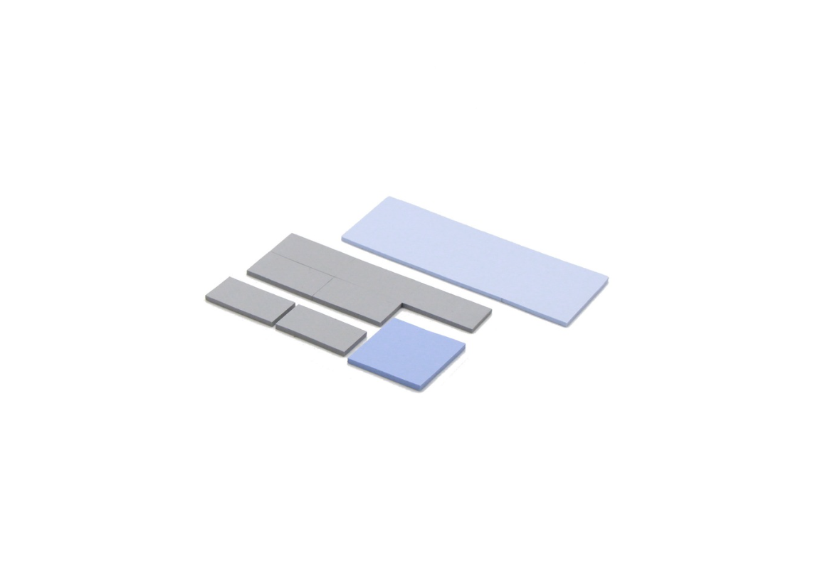
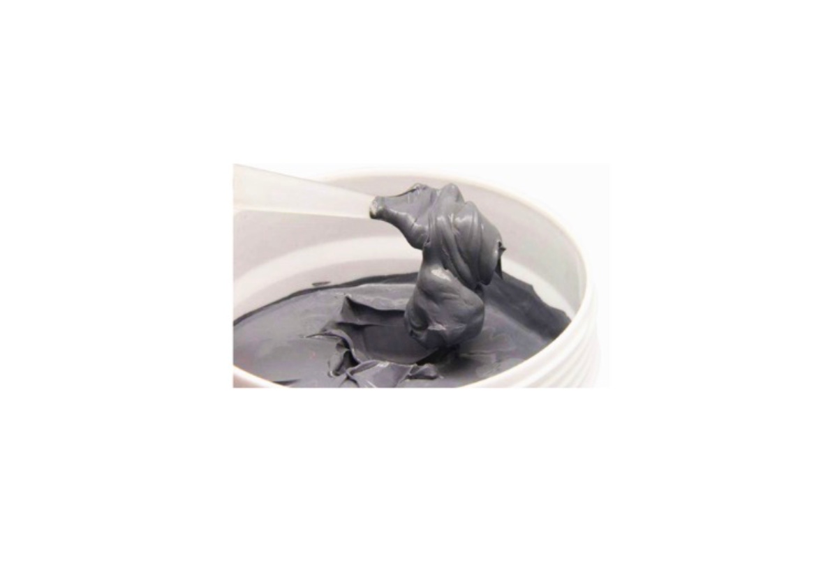
Thermal gap fillers and pads, typically in the 1–4 W/m·K range for standard commercial grades, work well at power amplifier and baseplate interfaces where consistent thickness and ease of rework during assembly matter. Thermal greases and gels, often reaching 3 W/m·K or higher, suit automated high-volume production where thin bond lines and low contact resistance are priorities — though grease's long-term stability under cycling deserves scrutiny for outdoor, non-serviceable deployments. Phase change materials, generally in the 3–8 W/m·K range once activated, deliver stable performance under repeated thermal cycling with minimal pump-out or migration, making them a strong fit for sealed outdoor modules. Graphite films provide strong in-plane heat spreading in space-constrained enclosures, helping balance temperature distribution across a module rather than serving as the primary interface material at a single hot component.
Matching the right type to a specific interface depends on that location's power density, assembly method, and environmental exposure — not on picking a single "best" material and applying it uniformly across the module.
Case Study: Solving an RRU Power Amplifier Hotspot
A telecom equipment manufacturer faced hotspot issues at the transistor baseplate within an RRU power amplifier. The existing TIM had insufficient thermal conductivity, resulting in excessive temperature rise during peak transmission — the kind of gradual thermal margin erosion that often doesn't show up until a module is pushed to full load in the field.
The engineering team replaced the standard thermal pad with a high-conductivity silicone-based gap filler optimized specifically for thin bond lines and stable contact pressure at that interface. Operating temperatures dropped by 8–10°C as a result, leading to improved signal linearity and reduced system derating. The overall Mean Time Between Failures (MTBF) increased significantly, translating into measurably better network uptime and reliability — a concrete illustration of how a targeted material change at a single interface can shift outcomes at the system level.
Case Study: PCM Performance in Outdoor Small Cell Deployment
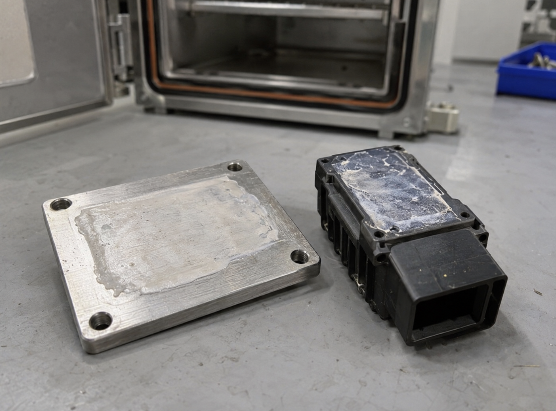
An outdoor small cell module deployed across a −40°C to +85°C climate range experienced TIM degradation after extended operation. The traditional silicone grease originally specified exhibited pump-out and delamination during repeated temperature cycles — a familiar failure pattern for grease-based interfaces in sealed, non-serviceable outdoor enclosures where reapplication isn't an option once the unit is in the field.
The engineering team replaced it with a phase change material formulated for strong adhesion and low thermal impedance, with a controlled melt transition that maintained stable contact across the full operating temperature swing. After 1,000 thermal cycles, the module maintained a stable thermal resistance below 0.3°C/W, with no visible delamination or pump-out during teardown inspection. That stability translated directly into consistent field performance and a longer service life for hardware that, once deployed on a pole or tower, isn't realistically going to be pulled for maintenance over a minor thermal issue.
Engineering Design Considerations
Getting the right material specified is only part of a reliable 5G thermal design — how it's applied matters just as much as what it is.
Even compression and bond line control determine whether a TIM actually performs at its rated specification. Uneven pressure or PCB warpage traps air pockets at the interface, raising thermal resistance and undermining reliability regardless of how good the material itself is on paper. Optimized TIM thickness balances competing pressures: a thinner bond line generally improves heat flow, but pushing thickness down too far can introduce mechanical stress at the interface — the right thickness accounts for both thermal performance and long-term durability under vibration and temperature cycling. Dielectric strength alignment deserves the same attention as thermal conductivity in RF and power modules, since insulation failure between isolated zones is just as serious a reliability problem as thermal underperformance. Surface preparation and cleanliness round out the list — even an excellent TIM can't compensate for a contaminated or uneven mating surface, which is why consistent cleaning and flatness standards matter as much in production as the material specification itself.
Validation and Reliability Testing
Confirming a TIM will actually hold up through a 5G module's service life requires validation that goes beyond a single initial measurement.
Thermal resistance (Rth) benchmarking under controlled pressure and temperature conditions provides the baseline quantitative picture of interface heat transfer efficiency. Environmental reliability testing — thermal cycling, humidity exposure, and vibration testing, typically referenced to relevant IEC standards and, for telecom-specific hardware, Telcordia GR-487 criteria for outdoor equipment enclosures — confirms the material withstands the combined stresses of actual field deployment rather than just a single controlled variable. Long-term aging and outdoor simulation, using accelerated testing under UV, moisture, and temperature fluctuation, helps predict real-world degradation before a module ever reaches a tower. Data-driven material selection — comparing measured Rth stability, adhesion retention, and dielectric strength across candidate materials — gives engineers a basis for choosing a TIM suited to both immediate thermal efficiency and multi-year reliability, rather than defaulting to whichever material has the highest headline conductivity number.
Common Mistakes in 5G TIM Selection
Optimizing for conductivity while ignoring environmental durability. A high-conductivity material that hasn't been validated for UV exposure or extended humidity cycling can perform excellently in a lab and still degrade within a year or two in an outdoor deployment — durability data deserves the same scrutiny as the conductivity spec.
Specifying grease for sealed, non-serviceable outdoor modules. As the case study in section 6 illustrates, grease's pump-out risk under thermal cycling is a poor fit for hardware that can't realistically be serviced once installed. PCM or gap filler alternatives remove this failure mode rather than just reducing its likelihood.
Treating dielectric strength as secondary to thermal performance. In compact modules where RF and power sections sit close together, an insulation failure is just as disruptive as a thermal one — verifying dielectric breakdown voltage against the specific isolation requirement at each interface shouldn't be an afterthought to the conductivity comparison.
FAQ
Q: How does TIM selection for 5G base stations differ from general power electronics applications?
The core selection logic is similar, but 5G hardware layers on additional requirements less common elsewhere: sustained outdoor environmental exposure across a wide temperature range, tight electrical isolation between closely packed RF and power sections, and long, unattended service life expectations once equipment is deployed on a tower or pole. These combine to push material selection toward higher-durability, lower-maintenance-risk options than a comparable indoor application might require. For general power electronics selection criteria, see How to Select Thermal Interface Materials for Power Inverter Designs.
Q: What additional parameters matter for outdoor 5G deployments specifically?
Beyond standard thermal and electrical specs, request UV resistance data, humidity cycling performance, and the material's full rated temperature range — verified at both the cold and hot extremes, not just the maximum. Compression set behavior over extended outdoor service life is also worth confirming for any TIM specified in a sealed, non-serviceable enclosure.
Q: Is phase change material always the right choice for outdoor small cell modules?
Not universally — PCM performs well specifically where surfaces are reasonably flat and the interface benefits from PCM's re-wetting behavior across thermal cycles, as shown in section 6. For larger gaps or more irregular surfaces, a gap filler or pad may be the more practical choice despite PCM's strong cycling stability, since PCM's conformability range is narrower than a dispensed gap filler's.
Conclusion
As 5G networks push toward higher frequencies and smaller form factors, thermal reliability increasingly separates equipment that performs consistently in the field from equipment that requires early replacement or costly redesign. Advanced thermal interface materials help reduce junction temperatures, preserve signal integrity, and extend service life — particularly in the compact, outdoor-deployed hardware that defines much of current 5G infrastructure.
Addressing thermal design early in module development, with material selection validated against real environmental and electrical requirements rather than conductivity alone, avoids the costly field corrections that come from discovering a thermal margin problem after deployment. For related selection guidance applicable to other power-dense telecom and industrial applications, see How to Select Thermal Interface Materials for Power Inverter Designs.
Contact TaxoTape® to discuss TIM selection for your 5G base station design →