Welcome to Taxo Tape
PCM vs. Thermal Pads: How to Choose the Right TIM for Power Electronics
Introduction
Thermal interface material selection rarely gets the attention it deserves — until something fails.
In high-power electronics, the gap between a component and its heat sink is never perfectly flat. Microscopic surface irregularities trap air, and air is a poor conductor of heat. TIMs exist to fill those gaps. But not all TIMs behave the same way under real operating conditions, and choosing the wrong one can quietly degrade system performance over months or years before the problem becomes obvious.
Phase change materials (PCMs) and silicone thermal pads are two of the most widely used TIM categories in power electronics — inverters, UPS systems, EV chargers, and industrial power supplies. They serve the same basic function but work differently, cost differently, and suit different assembly processes.
This article breaks down the practical differences between the two, with enough technical detail to inform a real material selection decision.
What Is a Phase Change Material (PCM)?
A PCM is solid at room temperature and softens — without fully melting — when it reaches operating temperature, typically between 45°C and 65°C depending on the formulation. As it softens, it flows slightly to conform to microscopic surface features, eliminating air pockets and creating a very thin, uniform bond line.
Key technical characteristics:
Thermal conductivity: typically 3–8 W/m·K (some high-performance grades reach higher)
Bond line thickness (BLT): 20–80 µm under typical clamping pressure
Phase transition temperature: 45–65°C (product-dependent)
Form factor: supplied as sheets, films, or pre-applied coatings on heat sinks
Because PCMs flow and wet the surface during operation, they can achieve thermal resistance values comparable to thermal greases — but without the long-term pump-out risk that makes greases problematic in cycling applications.
The tradeoff is process sensitivity. PCMs require consistent clamping pressure during assembly to perform as specified. In low-volume or manual assembly environments, maintaining that consistency adds process complexity.
What Is a Silicone Thermal Pad?
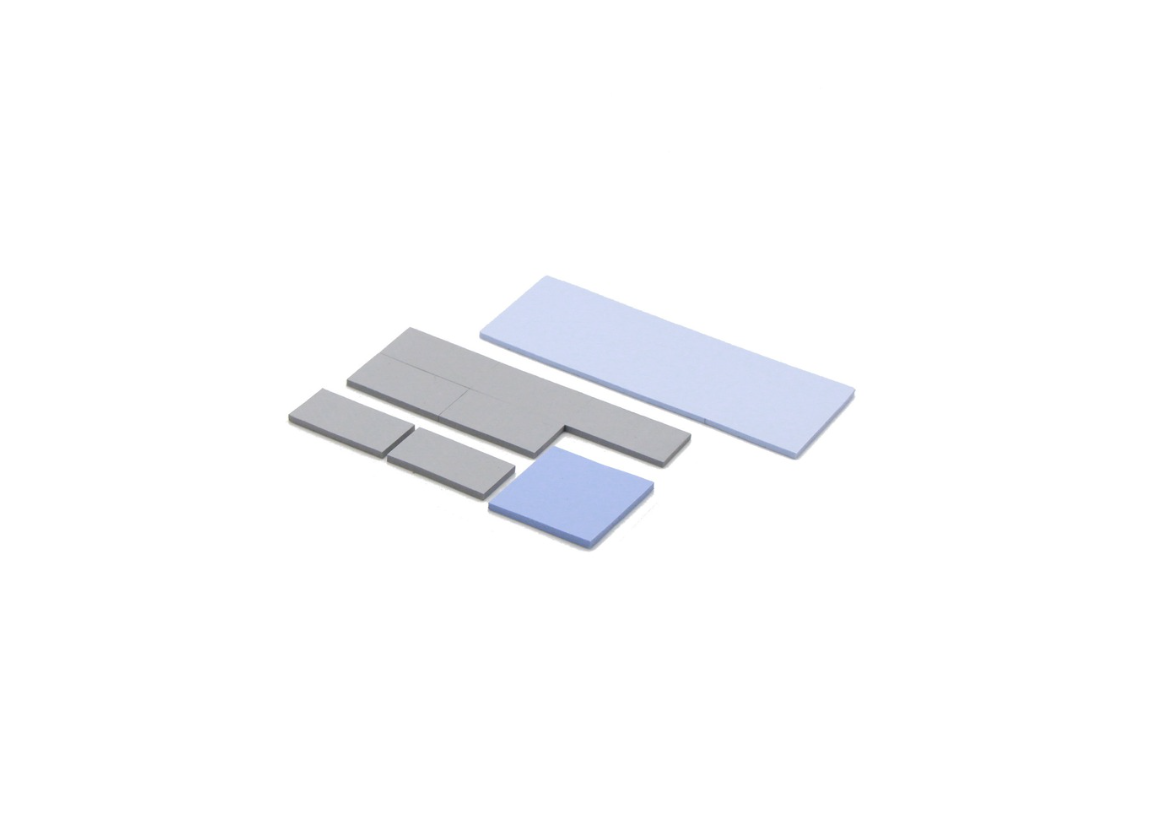
A silicone thermal pad is a pre-formed, compliant sheet that compresses under mounting pressure to fill the gap between two surfaces. Unlike PCMs, pads do not change phase — they rely on mechanical compliance and softness to conform to surface irregularities.
Key technical characteristics:
Thermal conductivity: typically 1–6 W/m·K (standard grades 1–3 W/m·K; high-performance grades 4–6 W/m·K)
Thickness range: 0.3–5 mm (selected based on gap size)
Electrical insulation: typically 3–10 kV/mm dielectric strength (most grades)
Hardness: Shore 00 20–60 depending on formulation
Pads are forgiving. They accommodate larger gaps, uneven surfaces, and varied component heights without special process controls. This makes them the default choice in many industrial and commercial power electronics designs — straightforward to handle, easy to replace, and available in a wide range of conductivity and thickness combinations.
The limitation is bond line thickness. Even a very soft pad maintains a minimum compressed thickness (typically 0.3–0.5 mm under standard pressure), which is significantly higher than what a PCM achieves. That thicker bond line translates directly into higher thermal resistance.
Head-to-Head Comparison
The table below reflects typical performance ranges across standard commercial grades. Actual values depend on specific product formulation, surface condition, and assembly pressure.
| Parameter | Phase Change Material | Silicone Thermal Pad |
|---|---|---|
| Thermal conductivity | 3–8 W/m·K | 1–6 W/m·K |
| Bond line thickness | 20–80 µm | 0.3–3 mm |
| Thermal resistance | Very low | Low to moderate |
| Electrical insulation | Usually requires separate layer | Built-in (most grades) |
| Phase transition | 45–65°C | None |
| Pump-out risk | Low | Low to medium (long-term) |
| Surface conformability | Excellent (after phase change) | Good (mechanically compliant) |
| Assembly complexity | Moderate — requires controlled pressure | Low — place and clamp |
| Reworkability | Moderate | Easy |
| Relative cost | Higher | Lower |
What the numbers mean in practice:
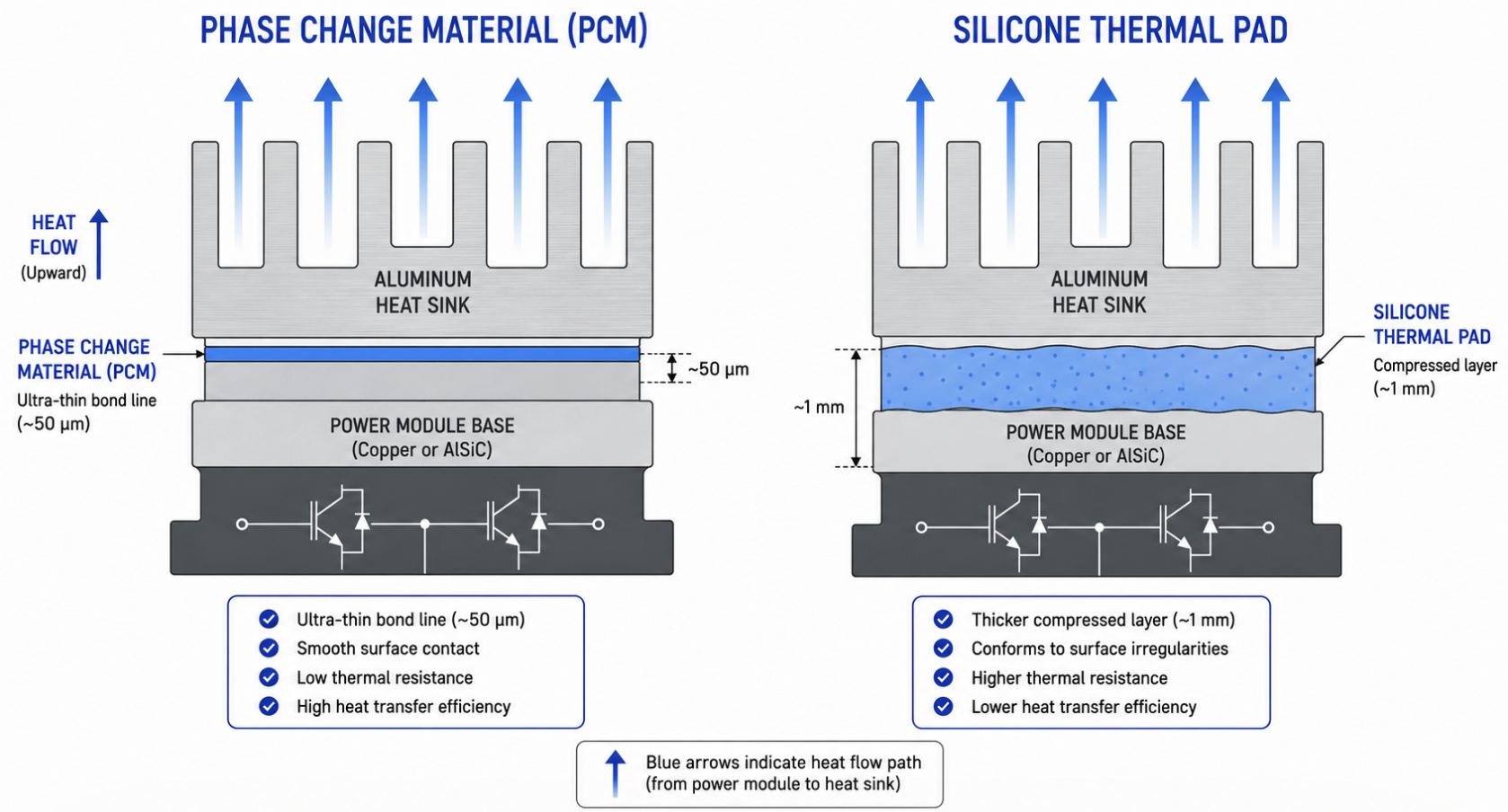
The bond line thickness difference is the most consequential factor for thermal performance. A PCM at 50 µm BLT versus a pad at 1 mm BLT — even if both have similar bulk conductivity — will produce meaningfully different thermal resistance values at the interface. For high-power-density designs where every degree of junction temperature matters, this gap is significant.
On the other hand, the pad's built-in electrical insulation eliminates a design step in high-voltage applications. IGBTs and MOSFETs operating at bus voltages above 400V typically require dielectric isolation between the device case and heat sink. Most thermal pads provide this without additional components, while PCM assemblies often need a separate insulating layer — adding cost and interface resistance.
When to Choose PCM
PCM makes the stronger case when thermal performance is the primary constraint and the assembly process can support it.
Consider PCM when:
Power density is high. Designs running above 10–15 W/cm² heat flux benefit from PCM's lower bond line thickness. At those power levels, the difference between 50 µm and 1 mm BLT is measurable in junction temperature — often 5–15°C depending on conductivity and geometry.
Long service life is required. In applications with 10+ year design life targets — industrial inverters, grid-tied power supplies, EV charging infrastructure — PCM's stability under thermal cycling outperforms most pad materials. Pads can gradually harden or lose compliance; PCM re-wets the surface each operating cycle.
Surfaces are relatively flat. PCM performs best when surface roughness is below 10 µm Ra and bow/warp is controlled. On well-machined heat sinks and standard power module bases, PCM delivers its designed performance. On rough or uneven surfaces, the performance advantage narrows.
Production is automated or semi-automated. Consistent clamping torque is easier to control in a fixture-based assembly line than in manual operations. If your process already torques fasteners to specification, PCM adds minimal complexity.
When to Choose Thermal Pad
Thermal pads remain the right answer in a large share of real-world applications — not because they are a compromise, but because the design conditions favor them.
Choose a thermal pad when:
Gap size is large or variable. If component height variation across a board exceeds 0.5 mm, or if the design gap is 1 mm or more, pads are the practical solution. PCMs cannot bridge large gaps reliably; pads can be specified in the exact thickness needed.
Electrical insulation is required and simplicity matters. A single thermal pad with 5 kV/mm dielectric strength replaces both a TIM and a separate insulating layer. For IGBT modules, power modules, and high-voltage inverter boards, this simplifies the BOM and assembly.
Assembly is manual or low-volume. Pads are peel-and-place. There is no phase transition to manage, no pressure specification to hit precisely, and no risk of material flowing to unintended areas. For prototyping, small-batch production, or field service replacement, pads are the lower-risk choice.
Cost targets are tight. In price-competitive markets — commodity LED drivers, entry-level UPS units, consumer power supplies — thermal pads at 1–3 W/m·K often provide sufficient thermal performance at a fraction of the PCM cost.
Common Selection Mistakes
Selecting by W/m·K alone.Thermal conductivity is one input, not the output. Two materials with identical conductivity but different bond line thicknesses will produce different thermal resistance values at the interface. Evaluate total interface thermal resistance — including contact resistance — not bulk conductivity.
Skipping assembly process validation.A material that performs well in a lab press fixture may behave differently on a production line with variable torque, mixed component heights, or operator-dependent placement. Validate TIM performance under your actual assembly conditions, not ideal ones.
Treating initial test data as long-term performance.Both PCMs and pads can drift over time under thermal cycling, vibration, and humidity. A TIM that passes initial thermal resistance measurement may degrade after 500 cycles. Request reliability data — thermal cycling test results, pump-out measurements, compression set data — before finalizing material selection for production.
TaxoTape® Solutions
TaxoTape® supplies both phase change materials and silicone thermal pads for industrial power electronics applications, including inverters, UPS systems, EV chargers, and LED driver assemblies.
Available formats include standard sheet sizes and custom die-cut parts to component dimensions. Full technical documentation — TDS, RoHS declaration, and test reports — is provided with sample and production orders.
If you are evaluating TIM options for a current design, we can recommend specific grades based on your gap size, power density, and assembly process. Sample quantities are available for qualification testing.
Conclusion
PCM and thermal pads are not competing products — they address different design conditions. PCM delivers lower thermal resistance and better long-term stability in high-power, flat-surface, automated-assembly applications. Thermal pads offer simpler handling, built-in electrical insulation, and better gap accommodation where those factors matter more than squeezing out the last degree of junction temperature.
The selection decision becomes straightforward once power density, gap geometry, electrical requirements, and production process are defined. Where those parameters sit in the middle — moderate power, moderate gap, mixed requirements — testing both options under actual operating conditions remains the most reliable path to a final decision.
Need help selecting the right TIM for your application? Contact TaxoTape® for technical support or sample request →
FAQ
Q: At what power density should I consider switching from thermal pads to PCM? As a general guideline, designs above 10–15 W/cm² heat flux often benefit from PCM's lower bond line thickness. Below that threshold, a high-conductivity thermal pad typically provides adequate performance at lower cost.
Q: Do PCMs require a separate electrical insulation layer? Most PCM formulations are not inherently electrically insulating. In high-voltage applications, a separate dielectric layer — or a thermally conductive, electrically insulating PCM grade — is required. Confirm dielectric specifications with your supplier before use.
Q: How do I know if a thermal pad will hold up over 10 years of thermal cycling? Request accelerated thermal cycling test data from the supplier — typically JEDEC or IEC standard profiles. Look for compression set measurements after cycling and confirm the pad retains compliance within acceptable limits for your application.
Q: Can TaxoTape® supply custom die-cut TIMs?Yes. Both PCM sheets and thermal pads are available in custom die-cut formats to match component or module dimensions. Contact us with your drawing or dimensions.