Welcome to Taxo Tape
Phase Change Material vs. Thermal Pad: How to Choose the Right TIM for Power Electronics
Why This Choice Matters More Than Most Engineers Expect
Thermal interface material selection rarely gets the attention it deserves early in a design cycle. Engineers lock in the topology, finalize the gate driver, specify the heatsink — and then, almost as an afterthought, drop in a thermal pad from a familiar supplier. It works well enough during bench testing, and no one revisits it.
That approach catches up with you in the field. Thermal resistance at the interface between a power device and its heatsink can account for 20–40% of the total junction-to-ambient thermal path, depending on the design. The difference between a well-matched TIM and a poorly chosen one isn't just a few degrees — it can be the margin between a module running at 85% of rated load indefinitely and one that throttles or fails prematurely under real operating conditions.
Phase change materials and thermal pads are the two most commonly specified TIM formats for high-power electronics. They look similar in catalog listings — both come as thin sheets, both sit between component and heatsink — but they operate on fundamentally different principles. Knowing which mechanism fits your application, and why, is what this article is for.
What Each Material Actually Does
2.1 Phase Change Materials (PCM)
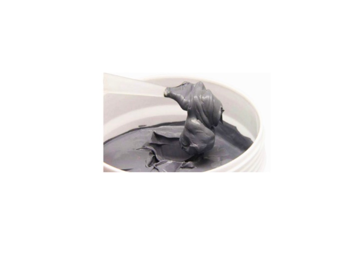
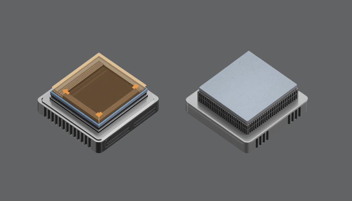
A phase change material is a solid at room temperature. Handle it, cut it, pre-apply it to a component surface — it behaves like a dry film. But once the device heats up and the interface temperature crosses the material's transition point (typically somewhere between 45°C and 60°C for most industrial-grade PCMs), it softens and flows. Not into a liquid — it becomes a viscous, paste-like state that conforms intimately to both mating surfaces.
This is the core value proposition. Surface irregularities, microscale roughness, slight warpage across a wide IGBT baseplate — the PCM flows into all of it. Air pockets, which are the primary enemy of thermal conductivity at an interface, are displaced. The result is a bond line that behaves much more like a continuous thermal conductor than a mechanical assembly.
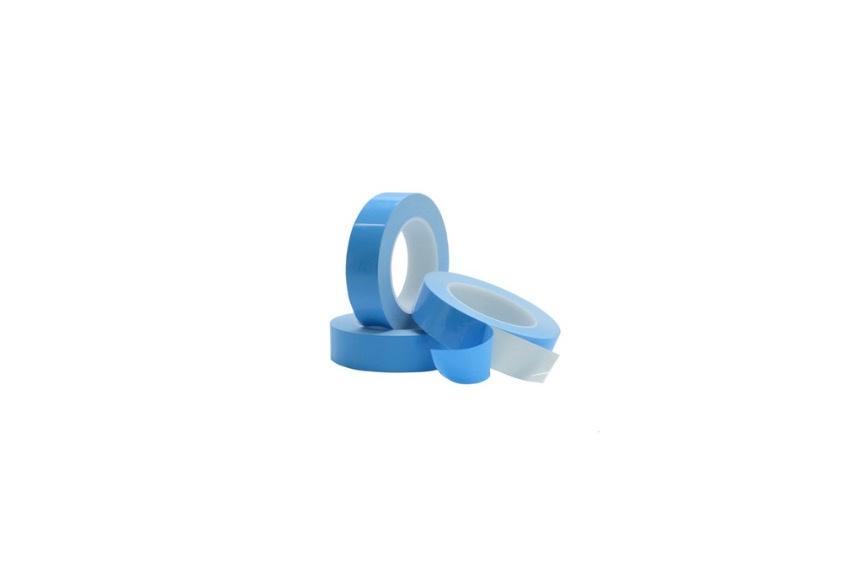
Typical thermal conductivity for PCM products ranges from 3 to 7 W/m·K, with some higher-performance formulations reaching above that using silver or boron nitride fillers. Thickness in the activated state is usually between 0.1 and 0.5 mm — among the thinnest achievable bond lines of any preformed TIM. Many PCMs come in tape-backed formats that allow pre-application at the factory, which suits high-volume automated assembly well.
The limitation is the flip side of that same mechanism: once the PCM activates and wets both surfaces, it adheres. Disassembly is possible but messy. The material doesn't cleanly release the way a thermal pad does, and residue cleanup is more involved.
2.2 Thermal Pads (Silicone-Based)
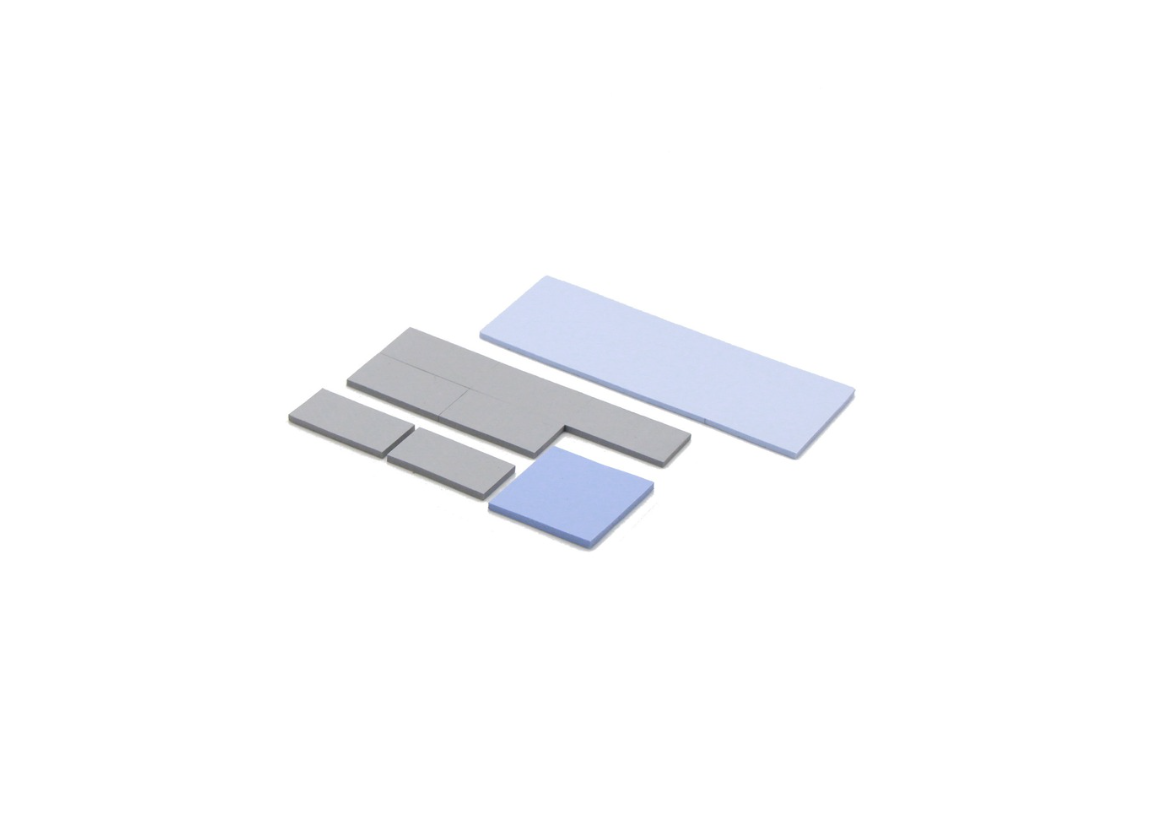
A silicone thermal pad is a preformed elastomeric sheet, typically filled with thermally conductive particles — aluminum oxide (Al₂O₃), boron nitride (BN), or aluminum nitride (AlN) depending on the performance and dielectric requirements of the design. It sits between component and heatsink, and when the assembly is bolted together, the mechanical compression forces the pad to conform to both surfaces.
Conformability here is a function of the pad's hardness (Shore OO or Shore A, depending on the product) and the clamping force applied. The softer the pad, the less force required to achieve good contact — but softer pads are also more susceptible to cold flow and pump-out over time under sustained mechanical load and thermal cycling.
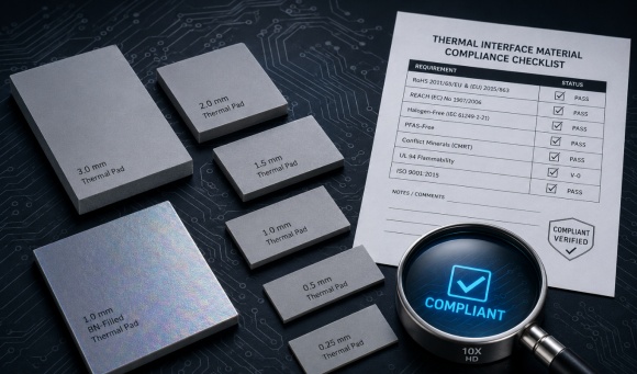
Thermal conductivity varies widely across the pad category: 1 to 12 W/m·K is a realistic range for standard silicone-based products, with high-performance BN-filled pads reaching the upper end. Thickness options span from roughly 0.3 mm to 5 mm or more, which makes pads practical for gap-bridging applications that PCM films simply can't address.
One property that distinguishes thermal pads from most other TIM formats is electrical insulation. Many pad formulations — particularly BN-filled types — offer high dielectric strength, making them suitable for applications where the thermal path also crosses an electrical isolation boundary.
Head-to-Head: Key Performance Parameters
No single spec tells the full story, but comparing the two formats across the parameters that matter most to a design engineer gives a clearer picture of where each one belongs.
| Parameter | Phase Change Material | Thermal Pad |
|---|---|---|
| Thermal conductivity | 3–7 W/m·K (typical) | 1–12 W/m·K (grade-dependent) |
| Interface thermal resistance | Very low (post-activation) | Low to moderate (compression-dependent) |
| Minimum bond line thickness | ~0.1 mm | ~0.3 mm |
| Usable thickness range | 0.1–0.5 mm | 0.3–5.0 mm+ |
| Operating temperature range | Limited below activation point | −40°C to 200°C+ (formulation-dependent) |
| Surface conformability | Excellent (flows to fill gaps) | Good (requires adequate clamping) |
| Electrical insulation | Generally low | Available (BN-filled grades) |
| Reworkability | Difficult | Easy — peel and replace |
| Assembly process | Pre-apply, no mess at room temp | Cut-to-size, manual or semi-auto |
A note on thermal resistance: the numbers published in datasheets are measured under controlled laboratory conditions — specific pressure, surface finish, bond line thickness. Real-world performance can diverge significantly from those figures. A PCM activated at proper operating temperature on a well-prepared surface will typically outperform a thermal pad of equivalent conductivity, because the bond line is thinner and the surface contact fraction is higher. But that advantage assumes the device actually reaches the activation temperature consistently — a condition that isn't always guaranteed.
Where Phase Change Material Has the Edge
PCM is the stronger choice in a specific but important set of conditions.
The device runs hot, and it runs hot reliably. PCM's performance advantage is fully realized only after the phase transition occurs. If your power module — an IGBT stack in a three-phase inverter, a DC-DC converter in a telecom rectifier, a power stage in a high-frequency switching supply — operates with junction temperatures consistently above 70–80°C, the interface will spend most of its life in the activated state. That's where PCM delivers its lowest thermal resistance.
Bond line thickness is a constraint. In dense power module packaging, every tenth of a millimeter in the thermal stack matters. PCM films can achieve activated bond lines below 0.2 mm on smooth, flat surfaces — thinner than most thermal pad grades can reliably sustain under compression without pad material extruding laterally out of the interface.
Volume and assembly process favor it. Pre-applied PCM film eliminates a manual handling step on the production line. The component arrives with the TIM already attached, dry and stable at room temperature. No cut-to-size, no alignment during assembly, no risk of the pad slipping out of position. For high-volume automated production, this is a meaningful process advantage.
Ultra-low thermal resistance is the primary objective. When the application demands minimizing junction temperature above almost everything else — and surface flatness is well-controlled — PCM is difficult to beat at comparable thickness. The flowing mechanism achieves near-ideal surface contact that a preformed pad, regardless of softness, cannot match.
Where PCM starts to struggle: cold-start applications where the device may spend extended periods below the activation temperature, any design where field servicing or board-level component replacement is expected, and geometries where gap bridging beyond 0.5 mm is required.
Where Thermal Pads Have the Edge
Thermal pads cover a broader range of application conditions than PCM, which is precisely why they remain the default choice across most industrial power electronics designs.
Temperature profiles are unpredictable or include cold starts. UPS systems, outdoor inverters, motor drives in variable-load environments — these devices spend real time at low temperatures, including startup from ambient in winter conditions. A PCM that hasn't activated offers negligible conformability benefit. The pad, by contrast, performs consistently across its full operating range from the moment the assembly is bolted together. There's no activation threshold to clear.
Field serviceability is a design requirement. Any application where a technician might need to replace a power component — swapping a failed IGBT module in a UPS cabinet, replacing a driver board in industrial control equipment — benefits significantly from a reworkable TIM. Thermal pads peel cleanly from both surfaces. The replacement component can be installed with a fresh pad and the assembly is back in service. With PCM, disassembly is more involved, surface cleanup takes longer, and there's greater risk of surface damage if the technician isn't experienced with the material.
The gap is too large for a film. PCM products are practical up to roughly 0.5 mm bond line thickness. Beyond that, bridging the gap between a component and heatsink — across component height variation, PCB warp, or mixed-height device populations on a single heatsink — requires the mechanical bulk that only a formed pad can provide. Thermal pads from 1 mm to 3 mm or thicker are standard catalog items. No PCM equivalent exists for that range.
Electrical isolation is required along the thermal path. This is a decisive factor in many power electronics designs. Boron nitride-filled silicone pads offer thermal conductivity in the 6–10 W/m·K range combined with dielectric strength that can exceed 10 kV/mm — allowing the pad to simultaneously conduct heat and block current. PCM products are generally not formulated for this dual function. When the heatsink is chassis-grounded and the component baseplate carries a switching voltage, the TIM must insulate. Thermal pads handle this cleanly; PCM typically does not.
Component geometry is irregular or clamping force is inconsistent. Soft thermal pads — Shore OO 30 to 60 — can conform to mild surface irregularities under relatively low clamping pressure. For assemblies where bolt torque is difficult to control precisely, or where the mating surfaces have significant roughness or curvature, a pad with sufficient compliance reduces the sensitivity of thermal performance to assembly variation. PCM, by contrast, relies on the melt process rather than mechanical compliance, so pre-melt surface contact quality is more critical.
The Hybrid Approach: When Engineers Use Both
Some high-performance designs specify a PCM layer on top of a thin, electrically insulating thermal pad — capturing the conformability advantage of the phase change material while the pad handles the isolation requirement that PCM alone can't meet.
This is more common in IGBT module assemblies for industrial inverters and traction applications than in general power electronics. The pad provides the dielectric barrier and a stable mechanical substrate; the PCM film on top flows at operating temperature to eliminate interfacial air gaps on the component side.
The tradeoff is real: every additional layer adds thermal resistance, and the assembly becomes harder to rework. For most standard industrial designs — LED drivers, UPS, motor drives in the 10 kW to 200 kW range — the complexity isn't justified. A well-specified BN thermal pad handles both functions adequately. The hybrid approach is worth considering only when thermal budgets are tight enough that the marginal reduction in interface resistance from the PCM layer makes a measurable difference, and when the production process can support the additional material handling.
Four Questions to Ask Before You Specify
Rather than starting from a thermal conductivity number, the selection process is more reliable when driven by application behavior. These four questions will narrow the field quickly.
Does your device reliably reach the PCM activation temperature during normal operation?Check your thermal simulation or measured junction data. If the interface temperature consistently exceeds 55–60°C under typical load, PCM is viable. If the device spends significant time below that threshold — either due to light-load operation, intermittent duty cycles, or cold ambient conditions — the PCM advantage may never fully materialize in service.
Will the TIM need to be replaced in the field?Design for the maintenance scenario, not just the first installation. If your end customer's service team will be handling this assembly — even occasionally — the added complexity of PCM removal and surface preparation under field conditions is a real cost. Thermal pads make this a non-issue.
What is the gap between your mating surfaces, and how consistent is it?Measure the actual gap range across your production tolerance stack — component height variation, PCB thickness tolerance, heatsink flatness. If the gap varies by more than 0.3–0.4 mm across a batch, a formed pad with appropriate compliance will deliver more consistent thermal performance than a fixed-thickness PCM film.
Is electrical isolation required at the interface?If yes, reach for a BN-filled thermal pad unless there's a compelling reason not to. This single requirement eliminates most PCM options from consideration without further analysis needed.
If your answers point in opposite directions — say, the thermal profile favors PCM but serviceability argues against it — weight the answer that's harder to work around in practice. Serviceability issues in the field are typically more expensive than a few degrees of margin given up at the design stage.
Specification Is the Starting Point, Not the Answer
Thermal conductivity is the number printed largest on every TIM datasheet, and it's the least sufficient predictor of real-world interface performance. Bond line thickness, surface roughness (Ra), clamping pressure, and the flatness of both mating surfaces all have significant influence on the actual thermal resistance achieved in an assembled design — sometimes more than the material's bulk conductivity.
A PCM film rated at 6 W/m·K on a well-prepared, flat surface under correct assembly conditions will outperform a thermal pad rated at 8 W/m·K on a warped baseplate with insufficient clamping torque. The material matters, but so does the context it goes into.
The most reliable way to validate a TIM selection before committing to it in production is to test samples in your actual assembly — your surfaces, your clamping geometry, your thermal load profile. Simulation gives you a starting point; measured bond-line temperature rise gives you the answer.
If you're working through a material selection decision and want to discuss the specifics of your application — power dissipation, gap range, surface conditions, isolation requirements — we're glad to help narrow down the options. Reach out with your parameters, and we can suggest materials worth sampling.