Welcome to Taxo Tape
TIM Selection for Power Inverters: Thermal Pads, PCM, or Gap Filler?
Introduction
Power inverters operate under a specific set of thermal conditions that make TIM selection more consequential than in most other electronics applications. Switching losses in IGBT and MOSFET modules generate concentrated heat flux at the device-to-heat-sink interface. Operating cycles — from standby to full load and back — create repeated thermal expansion and contraction at that interface. And in industrial, renewable energy, and EV charging applications, the inverter is expected to maintain thermal performance for 10–15 years without internal maintenance access.
These conditions mean that a TIM which performs adequately in initial testing can still fail the application through pump-out under cycling, gradual hardening, or loss of contact pressure over years of sustained compression. The selection decision needs to account for long-term behavior under inverter-specific operating conditions, not just initial thermal resistance.
This article focuses on practical TIM selection for the interfaces that matter most in power inverter design, with specific material comparisons and a decision framework built around inverter operating requirements.
Where TIMs Are Applied in a Power Inverter
Understanding which interfaces need TIMs — and what each one demands — is the starting point for material selection.
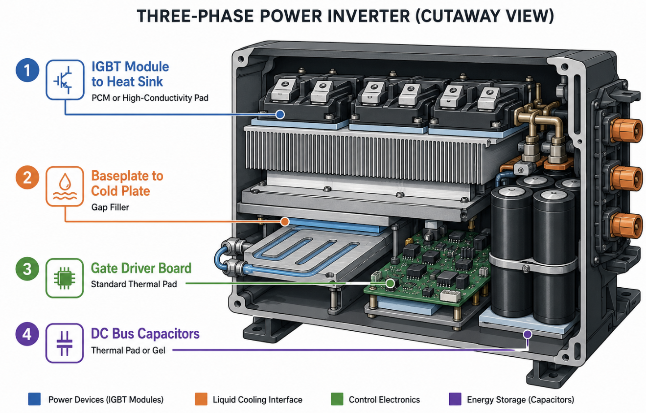
IGBT or MOSFET module to heat sink. This is the primary thermal path and the most demanding interface in the system. Heat flux at this location can reach 15–30 W/cm² or higher in high-power designs. The TIM here needs to minimize thermal resistance while withstanding thousands of thermal cycles over the inverter's service life. Electrical insulation is typically required, as the module case may be at switching potential.
Power module baseplate to cold plate or chassis. In liquid-cooled inverter designs, power modules mount to a cold plate. This interface requires low thermal resistance and consistent contact pressure over the full baseplate area — often 50–200 cm² for large modules. Gap uniformity across this area is a practical assembly challenge.
DC bus capacitors and gate driver boards. These components generate less heat than the main switching devices but still require thermal management. The requirements here are less demanding — moderate conductivity, electrical insulation, and ease of assembly take priority over achieving minimum thermal resistance.
Auxiliary power supplies and control boards. Similar to capacitors and gate drivers, moderate thermal requirements, assembly simplicity, and electrical isolation are the governing factors rather than thermal performance optimization.
Key Selection Parameters for Inverter TIMs
Thermal conductivity (W/m·K) is the most commonly referenced parameter but not the most useful one in isolation. It tells you the material's bulk heat transfer capability without accounting for the thickness at which it will be used.
Thermal resistance (°C·cm²/W) is the more directly applicable metric:
R = thickness (m) ÷ conductivity (W/m·K) × 10⁴
At the IGBT-to-heat-sink interface, target thermal resistance values are typically 0.1–0.3 °C·cm²/W for high-performance designs. At auxiliary component interfaces, 0.5–1.5 °C·cm²/W is usually acceptable.
Electrical insulation (dielectric strength). IGBT modules in industrial inverters commonly operate at DC bus voltages of 600–1200V. The TIM at the module-to-heat-sink interface needs adequate dielectric strength to maintain isolation between switching potential and the grounded heat sink. Minimum dielectric strength requirements depend on the specific voltage level and applicable safety standards — verify against IEC 62477 or relevant product standard for your design. Standard silicone thermal pad grades typically provide 8–15 kV/mm; BN-filled grades reach 15–25 kV/mm.
Thermal cycling stability. A grid-tied solar inverter or EV charger cycling multiple times daily over 15 years accumulates roughly 10,000–20,000 thermal cycles. The TIM needs to maintain thermal resistance within acceptable limits across that full cycle count — request accelerated thermal cycling data (typically referenced to IEC or JEDEC cycling profiles) from suppliers, not just initial thermal resistance measurements.
Bond line thickness (BLT). Every additional 0.1 mm of BLT adds approximately 0.03–0.1 °C·cm²/W of thermal resistance depending on conductivity. At high-power-density interfaces, controlling BLT through material selection and mounting hardware design directly affects junction temperature margin.
TIM Options for Power Inverters
a. Silicone Thermal Pads
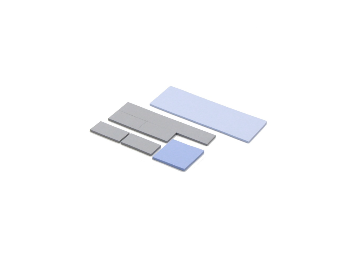
Silicone pads are the most widely used TIM in power inverter production — they balance thermal performance, electrical insulation, assembly simplicity, and cost in a format that works across a broad range of interfaces.
Thermal conductivity: 1–8 W/m·K (standard grades 1–3 W/m·K; high-performance grades 4–8 W/m·K)
BLT: 0.3–3 mm typical compressed range
Dielectric strength: 8–25 kV/mm depending on grade and filler
Best fit in inverters: auxiliary component interfaces, gate driver boards, DC bus capacitors, and IGBT module interfaces where gap size is 0.5 mm or greater. High-conductivity BN-filled grades extend pad suitability to primary IGBT interfaces in medium-power designs.
Limitation: at very tight, flat interfaces below 0.3 mm BLT, pads cannot match the thermal resistance achievable with PCM or grease. Compression set over long service life at sustained clamping load needs verification for 10+ year applications.
For the specific assembly considerations at IGBT module interfaces — torque control, cleaning procedures, and pressure distribution during mounting — see Thermal Interface Solutions in Industrial Inverter Systems.
b. Phase Change Materials (PCM)
PCMs are the preferred choice for primary IGBT-to-heat-sink interfaces in high-performance inverter designs — they combine grease-like thermal resistance with better long-term stability and cleaner assembly.
Thermal conductivity: 3–8 W/m·K
BLT: 20–80 µm after phase transition
Phase transition temperature: 45–65°C (confirm activation relative to your minimum operating case temperature)
Pump-out risk: low — material re-wets interface on each thermal cycle rather than migrating outward
Best fit in inverters: IGBT and MOSFET module interfaces in high-power designs where junction temperature margin is tight and long service life is required. Pre-applied PCM on heat sink surfaces suits automated inverter assembly lines.
Limitation: requires controlled clamping pressure during assembly. Does not accommodate large gaps — surfaces must be flat and within PCM's conformability range (typically surface roughness below 10 µm Ra).
c. Thermal Gap Fillers
Gap fillers are dispensable materials designed for interfaces where gap size or surface variation exceeds what pads or PCM can accommodate.
Thermal conductivity: 1–4 W/m·K typical for commercial grades
Gap accommodation: 0.5–10 mm
Form: single-component (1K) or two-component curing (2K)
Best fit in inverters: large baseplate-to-cold-plate interfaces in liquid-cooled designs, capacitor bank thermal management, and any interface with component height variation exceeding 0.5 mm. 2K curing gap fillers provide structural bonding in addition to thermal performance.
Limitation: lower conductivity ceiling than pads or PCM. 2K formulations add a process step (mixing and cure time management).
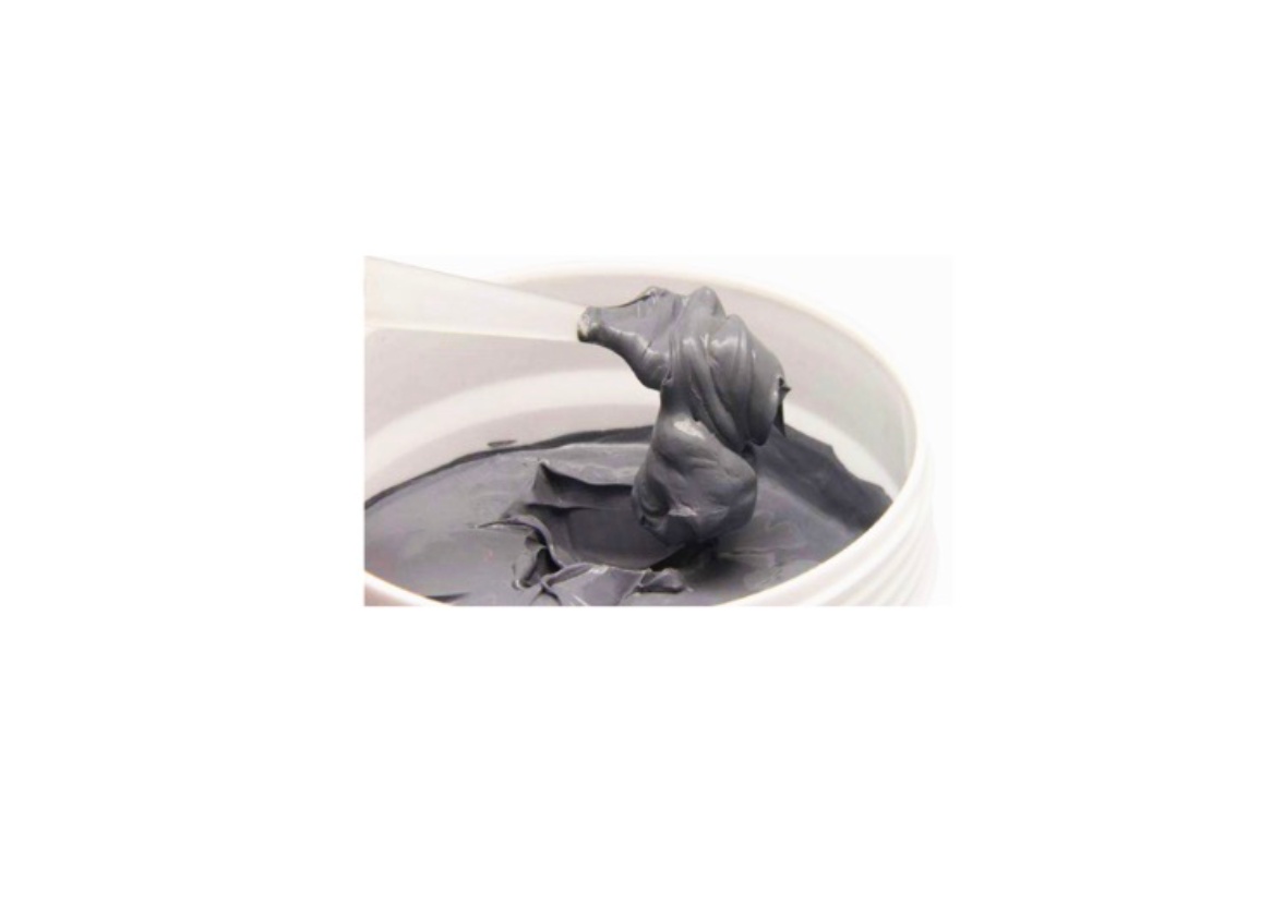
d. Thermal Grease
Grease achieves the lowest initial thermal resistance at tight, flat interfaces and remains in use for IGBT module applications — particularly where periodic maintenance access makes reapplication feasible.
Thermal conductivity: 3–10+ W/m·K
BLT: 20–100 µm achievable under controlled conditions
Best fit in inverters: IGBT interfaces in designs with maintenance access, or where initial thermal performance takes priority over long-term stability and the service interval allows reapplication.
Limitation: pump-out under thermal cycling degrades performance over time. Not appropriate for sealed, long-life inverter designs where reapplication is not possible. Production application consistency is difficult to control compared to pad or PCM formats.
Head-to-Head Comparison
| Parameter | Silicone Thermal Pad | PCM | Gap Filler | Thermal Grease |
|---|---|---|---|---|
| Thermal conductivity | 1–8 W/m·K | 3–8 W/m·K | 1–4 W/m·K | 3–10+ W/m·K |
| Typical BLT | 0.3–3 mm | 20–80 µm | 0.5–10 mm | 20–100 µm |
| Thermal resistance | Low–moderate | Very low | Moderate | Very low (initial) |
| Electrical insulation | Built-in (most grades) | Usually requires a separate layer | Grade dependent | Grade dependent |
| Thermal cycling stability | High | High | High | Moderate–low |
| Pump-out risk | None | None | None | Medium–high |
| Gap accommodation | Moderate | Low (flat surfaces only) | High | Low |
| Assembly method | Peel-and-place | Peel-and-place | Dispense | Dispense/manual |
| Production consistency | High | High | Moderate | Variable |
| Long-term reliability | High | High | High | Moderate |
| Relative cost | Lower | Higher | Moderate | Lower |
| Primary inverter use | Auxiliary + medium-power IGBT | High-power IGBT | Large gaps, cold plate | Maintainable IGBT |
Selection Decision Framework
The selection logic for inverter TIMs follows a sequence of questions, each one narrowing the field.
What is the heat flux at this interface?
Below 5 W/cm² — auxiliary components, control boards, capacitor banks — standard silicone thermal pads at 1–3 W/m·K typically provide sufficient thermal resistance margin. Above 10 W/cm² — IGBT and MOSFET primary interfaces at full rated power — the thermal resistance budget becomes tight enough that BLT and conductivity both need optimization. PCM or high-conductivity BN-filled pads are appropriate here; standard pads are not.
What is the gap size and surface condition?
Flat, machined surfaces with gaps below 0.3 mm: PCM delivers the lowest thermal resistance.
Moderate gaps of 0.3–2 mm with reasonable surface flatness: silicone thermal pads in matched thickness.
Large gaps above 2 mm, or significant component height variation: gap filler is the only practical option.
What are the electrical insulation requirements?
At 600V DC bus voltage and above, verify dielectric strength against your applicable safety standard. BN-filled pads and most silicone pad grades provide adequate insulation for most industrial inverter voltage levels. PCM typically requires a separate insulating layer at high-voltage interfaces — factor this into BLT and cost calculations.
What is the service life and maintenance profile?
Sealed inverter, 10+ year target, no maintenance access: eliminate grease. PCM, pads, and gap fillers all maintain stable performance without reapplication.
Serviceable inverter with periodic maintenance intervals: grease remains viable at primary IGBT interfaces if reapplication is factored into the maintenance schedule.
Decision summary in plain terms:
High-power IGBT, flat surface, sealed long-life inverter → PCM.
IGBT or auxiliary interface, moderate gap, standard production → silicone thermal pad.
Large gap, cold plate interface, or height variation → gap filler.
Serviceable design, tight flat interface, maximum initial conductivity → thermal grease.
Common Mistakes in Inverter TIM Selection
Beyond material selection, some of the most common inverter TIM problems in the field trace back to a small number of recurring failure patterns — see TIM Optimization in Industrial Inverters for a diagnostic framework covering the four failure modes that account for most field issues.
Evaluating conductivity without specifying BLT.
A material's W/m·K value means nothing without knowing the thickness at which it will operate. Two TIMs with identical conductivity but different BLT produce different thermal resistance at the interface, and BLT is directly controllable through material selection and mounting hardware design. Always calculate expected thermal resistance at compressed BLT, not bulk conductivity alone.
Using initial thermal resistance data to predict long-term performance.
A grease or pad that measures well in initial testing may degrade meaningfully after 5,000 thermal cycles. For inverters with 10+ year design life in cycling applications, request accelerated thermal cycling test data from suppliers — not just initial thermal resistance. The delta between initial and post-cycling performance is what determines long-term reliability.
Ignoring the mounting pressure variation in production.
TIM thermal resistance is pressure-dependent. If mounting torque varies across production units — which it does without controlled torque processes — BLT varies, and thermal resistance varies with it. For high-power interfaces where the junction temperature margin is tight, standardizing mounting hardware and torque specification is as important as the TIM material selection itself.
Specifying consumer or PC-grade TIM for industrial inverter applications.
Consumer thermal pads and greases are designed for the thermal cycling profiles and service lives of computers and consumer electronics — not industrial inverters running continuous duty cycles at elevated temperatures for a decade or more. Verify that your TIM supplier provides industrial-grade products with appropriate reliability testing data, not consumer-grade material at similar price points.
TaxoTape® Solutions
TaxoTape® focuses on thermal pads, phase change materials, gap fillers, and thermal grease for power inverter applications across industrial, renewable energy, and EV charging sectors.
Available grades include standard silicone thermal pads from 1–6 W/m·K, BN-filled high-performance pads for primary IGBT interfaces, PCM in sheet and pre-applied formats, and single and two-component gap fillers for cold plate and large-gap applications. All products are supplied with full technical documentation, including TDS, dielectric strength data, thermal cycling test reports, and RoHS declaration.
For inverter development programs, we support material selection from initial specification through sample qualification and production scale-up — including grade recommendations based on your specific heat flux, gap geometry, voltage level, and service life requirements.
Request samples or technical consultation →
Conclusion
TIM selection for power inverters is not a single decision — it is a series of interface-specific choices driven by heat flux, gap geometry, electrical insulation requirements, and service life targets.
Silicone thermal pads cover the majority of inverter interfaces adequately and remain the practical default for moderate heat flux and general-purpose positions. PCM earns its place at high-power IGBT interfaces where BLT and long-term stability both matter. Gap fillers solve the interfaces that neither pads nor PCM can handle. Grease retains a role in serviceable designs where its limitations are manageable within the maintenance schedule.
Getting these choices right at the design stage — rather than discovering thermal margin issues during qualification testing or field deployment — is where careful TIM selection delivers its real value.
Contact TaxoTape® to discuss TIM selection for your inverter design →
FAQ
Q: Can the same TIM grade be used across all interfaces in a power inverter?
Rarely. The heat flux, gap size, and electrical insulation requirements differ significantly between the IGBT primary interface, auxiliary component positions, and cold plate interfaces. Using a single grade across all positions typically means over-specifying at low-heat-flux locations and under-performing at the primary interface. An interface-by-interface selection approach produces better thermal and cost outcomes.
Q: How do I calculate the maximum allowable thermal resistance for my IGBT interface?
Start with the IGBT's maximum junction temperature rating (typically 150–175°C for Si IGBTs), subtract the expected heat sink temperature at maximum load, and subtract the thermal resistance contributions of the module itself (junction-to-case) and the heat sink (case-to-ambient or case-to-coolant). The remaining budget is the maximum allowable TIM thermal resistance. If this calculation leaves less than 0.2–0.3 °C·cm²/W for the TIM, PCM or high-conductivity BN-filled pads are necessary rather than standard grades.
Q: What thermal cycling standard should I use to validate TIM performance for an industrial inverter?
IEC 60068-2-14 (thermal shock) and IEC 60068-2-1/2 (cold and dry heat) are commonly referenced for industrial electronics. For power module-specific validation, JEDEC JESD22-A104 provides a widely used thermal cycling profile. Request supplier test data referenced to one of these standards rather than proprietary test conditions that may not reflect your operating environment.
Q: Is it necessary to use electrically insulating TIM at every interface in an inverter?
Not necessarily — only at interfaces where the component case is at a voltage potential different from the heat sink or chassis. Gate driver boards and control electronics mounted to a grounded chassis may not require insulating TIM if the component cases are also at ground potential. Verify the electrical potential at each interface in your design before specifying insulating versus non-insulating TIM grades.