Welcome to Taxo Tape
How to Evaluate and Compare TIM Suppliers: A Buyer’s Guide
Introduction
Comparing TIM suppliers looks like a simple exercise on paper: line up the datasheets, check the conductivity numbers, compare pricing. In practice, two materials quoted at the same W/m·K can land at noticeably different junction temperatures once they’re actually clamped into your assembly. Two suppliers selling what looks like the same product category can differ sharply in batch consistency, documentation quality, and how useful their technical team actually is once you have a real question.
Most of that gap comes from things a datasheet simply doesn’t capture: how the material behaves at your specific clamping pressure, how it holds up over your product’s real service life, whether the numbers on the sheet were measured under conditions anything like yours, and whether the supplier can hold that performance steady across production runs at your volume.
This guide is a framework for that earlier decision — narrowing a list of candidate suppliers down to the two or three worth taking further, before any of them enters formal qualification. It walks through thermal performance, mechanical properties, compliance, process fit, and supplier capability in roughly the order that each one tends to matter for a real sourcing decision.
Evaluation gets you a shortlist. It does not, by itself, get you to a production release decision — that’s a separate and more rigorous step covered in our guide on How to Qualify a TIM Supplier for Production: Steps, Tests, and Acceptance Criteria. Think of this guide as the filter that decides who’s worth qualifying in the first place.
Step 1: Start With Your Application, Not the Supplier’s Catalog
Evaluation should begin with what your assembly actually needs, not with whatever a supplier happens to list on their product page. Skip this step and comparison turns subjective fast — you end up favoring whichever supplier presented their numbers most persuasively, rather than whichever material actually fits.
Operating temperature and thermal load
Pin down the continuous interface temperature, the peak transient temperature under worst-case load, and the heat flux at the interface itself. These three numbers set your minimum conductivity requirement and the upper temperature limit the material has to survive. A pad rated for steady 80°C service isn’t automatically fine at an interface that spikes to 130°C under a transient — that distinction gets missed more often than it should.
What kind of component you’re cooling
Different components pull in different directions. Power module interfaces — IGBTs, SiC MOSFETs, diodes — usually care most about low thermal resistance and stability through repeated thermal cycling. LED driver interfaces often need low-volatility or silicone-free formulations specifically. PCBA-level parts frequently prioritize electrical insulation and the ability to rework a joint over squeezing out maximum conductivity.
Mechanical limits of the joint
Know your actual gap range — nominal plus tolerance — and the flatness and roughness of both mating surfaces. These numbers decide which material families are even on the table: a 0.05mm gap calls for something fundamentally different from a 1.5mm one, and a rough cast surface needs more conformability than a machined one does.
Pressure and assembly method
Write down the actual clamping force your assembly applies — from fastener torque, clip pressure, or enclosure contact, whatever’s relevant. This determines how much compression the material will see and whether it’ll achieve full contact under conditions you actually have, not conditions a supplier’s test rig happened to use. Without this number, comparing compression data across suppliers doesn’t mean much.
Step 2: Get the Thermal Performance Comparison Right
Conductivity and interface resistance are not the same thing
Thermal conductivity (W/m·K) describes heat moving through a uniform sample under lab conditions. Interface thermal resistance (°C·cm²/W) describes what actually happens at a real contact boundary — including resistance at both surfaces and the effect of bond line thickness. The second number is what decides your junction temperature; the first is just one input feeding into it.
The relationship, roughly:
R_interface = BLT (cm) ÷ conductivity (W/m·K)
But contact resistance at both surfaces adds on top of that calculation, and contact resistance depends on surface flatness, how compliant the material is, and your actual clamping pressure — none of which show up in a single conductivity figure.
Why a higher number on the datasheet doesn’t guarantee better results
A stiffer, higher-conductivity pad that doesn’t fully conform to your surface irregularities at your available clamping force will often produce higher total interface resistance than a softer, slightly lower-conductivity material that achieves genuine full contact. This is the most common reason engineers upgrade to a “better” TIM on paper and see junction temperature stay flat — or get worse.
What to actually ask suppliers for
Don’t settle for a datasheet conductivity number in isolation. Request:
A thermal resistance vs. pressure curve, showing how Rth shifts with clamping force at your target BLT — this tells you whether the material actually performs at the pressure you can apply, not just at the higher pressures some standard test fixtures use.
ASTM D5470 data specifically, since it’s the most widely used and comparable method for TIM resistance measurement. Confirm the numbers you’re looking at were generated this way — laser flash and other bulk-diffusivity methods can produce higher-looking figures that don’t translate cleanly to interface performance.
Performance at your compressed BLT, not nominal pad thickness — the thickness after clamping is what matters, not the thickness printed on the package.

Step 3: Look Past the Hardness Number Into Reliability
Hardness and compression behavior
Shore 00 hardness tells you roughly how much force it takes to compress a pad into contact. Softer material (Shore 00 20–35) conforms more easily at lower clamping force and handles surface variation better. Firmer material (Shore 00 45–60) holds its shape better under sustained load but needs more pressure to achieve full contact. Match this to your actual clamping force range — not to a general preference for “soft is better” or “firm is more stable,” because the right answer depends entirely on what your assembly can apply.
Ask for the compression force vs. thickness curve rather than a single hardness number. A curve shows behavior across the full range; a single number shows one point on it.
Compression set — the number suppliers skip most often
Compression set is the permanent thickness a pad loses after sustained compression at temperature. It’s reported as a percentage of original thickness, and it’s one of the more direct predictors of whether a pad still maintains adequate contact pressure and thermal resistance years into service.
A pad losing 25% of its thickness after 1,000 hours at 70°C will be measurably thinner under the same clamping load at end of life — meaning less contact pressure, higher thermal resistance, and a hotter junction than when the product shipped. For anything with a 5–10 year service target, ask for compression set data at your actual operating temperature, ideally at 1,000 hours and no less than 168.
Pump-out and migration over time
For dispensable materials — grease and gel — ask for pump-out resistance data from accelerated cycling. Standard grease formulations commonly show measurable pump-out somewhere in the 500–1,500 cycle range, though some premium formulations hold up better. For pads, check that the material doesn’t bleed or separate oil at elevated temperature in a way that could contaminate whatever’s sitting next to it.
Where supplier differences actually show up — batch consistency
This is often where the real gap between suppliers becomes visible. Ask for thickness tolerance data across batches — ±5% or tighter is a reasonable bar for anything where BLT control matters. Ask about hardness tolerance across batches too, and whether the supplier runs incoming inspection on raw material and outgoing inspection on finished parts. A supplier whose sample passes qualification cleanly but whose production runs drift is one of the more common, and more frustrating, sources of unexplained thermal variation once you’re at volume. (The formal process for verifying this across multiple production batches is covered in the qualification guide — this step is about gauging whether a supplier’s answer to the question gives you confidence, not running the full test yet.)
Step 4: Compliance Isn’t Optional — Check It Like It Isn’t
Electrical insulation
Where the component case sits at a voltage potential and the heat sink is grounded — or where you need isolation between two power nets — verify the TIM’s dielectric strength against your specific voltage and isolation requirement. Standard alumina-filled silicone pads typically run 8–15 kV/mm; BN-filled grades reach higher, around 15–25 kV/mm. Check the specific grade against your actual requirement under IEC 62477 or whatever product safety standard applies — don’t assume a general compliance claim covers your specific case.
Flame retardancy
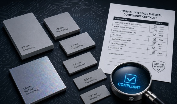
UL 94 V-0 is required for TIMs in most enclosed power electronics — inverters, UPS systems, LED drivers, EV charging gear. Confirm the certification applies to the exact grade and thickness you’re specifying, not a different thickness variant from the same product family that happens to carry the rating.
RoHS and REACH
For anything sold into the EU or most regulated markets, RoHS is a baseline, not a differentiator. Ask for a formal Declaration of Conformity rather than taking a verbal assurance at face value. If you have specific restricted-substance requirements beyond RoHS — halogen-free specs, SVHC limits under REACH — request a full material declaration and check it against your actual restricted substance list, not a generic compliance statement.
Low volatility and outgassing
For any TIM going into a sealed enclosure with optical components, relay contacts, or precision sensors — a common concern in LED driver and sealed outdoor electronics — ask for outgassing data to ASTM E595. The two values that matter are Total Mass Loss (TML) and Collected Volatile Condensable Materials (CVCM). Acceptable thresholds vary by application sensitivity; for optical-adjacent use cases, CVCM below 0.01% is a commonly referenced bar.
Step 5: Think About How the Material Will Actually Get Installed
Manual vs. automated assembly
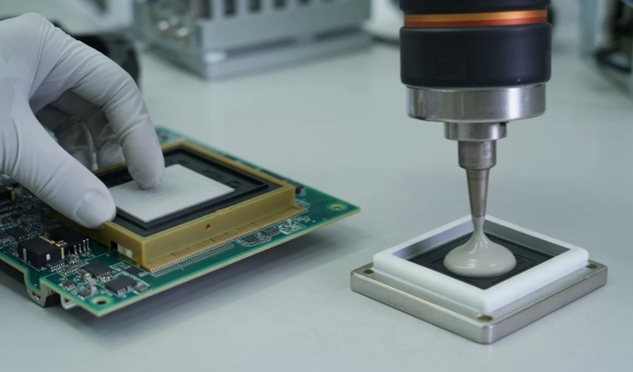
A TIM that’s easy to work with in small-batch manual assembly can turn into a real problem once you’re running an automated line. Worth asking directly: does the pad release cleanly from its liner without tearing or stretching? Can a vacuum gripper pick it up without deforming it? Is liner release force consistent across a full roll or sheet, not just the sample piece you tested? For dispensable materials, the equivalent questions are about viscosity — does it stay stable across your dispensing equipment’s operating temperature range, and does the material respond predictably to your dispense pressure and needle spec, run after run?
Can it be reworked
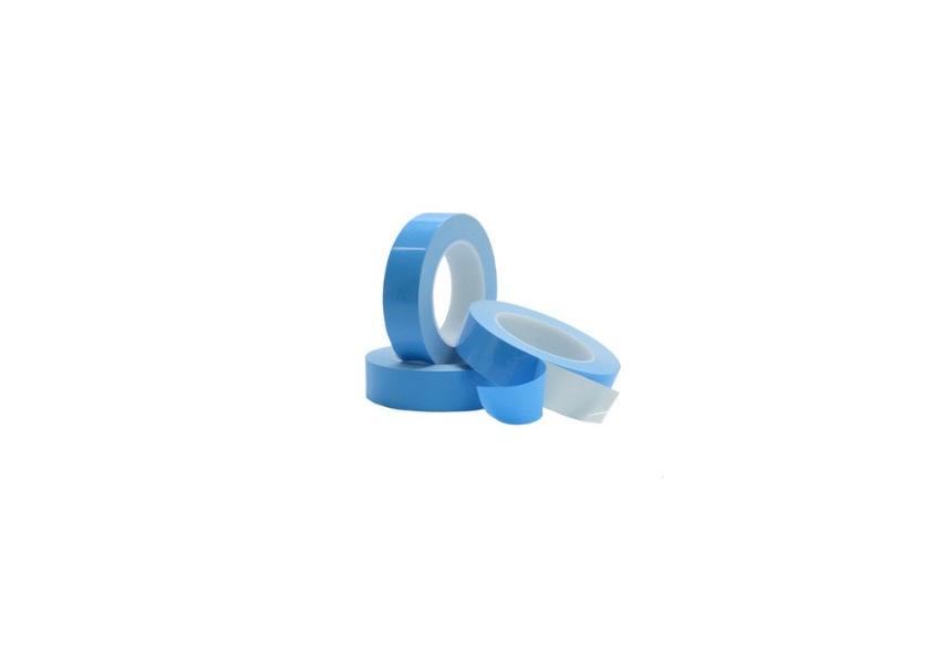
Anywhere a component might need replacing — during production rework or later in field service — the TIM has to come off without damaging the component or the heat sink surface underneath it. Silicone pads generally peel off both surfaces cleanly. Thermally conductive adhesive tapes need more force and often leave residue behind. Gap fillers that cure in place sometimes need solvent cleanup. If there’s any realistic chance of field service on the assembly, ask suppliers specifically how their material behaves during rework and what cleanup it requires — this is easy to overlook until the first repair ticket comes in.
Shelf life and storage
Get shelf life duration and storage temperature/humidity requirements for anything under evaluation. Two-component gap fillers and some PCM grades in particular can have narrow storage windows that add real logistics overhead — inventory has to move faster, or storage conditions have to be tighter than your warehouse normally handles. Check your actual storage environment against the supplier’s requirements before this gets locked into a spec, especially if you’re operating somewhere with real seasonal temperature swings.
Can they actually do custom formats
Standard sheet sizes rarely line up exactly with your assembly footprint. The ability to supply custom die-cut parts matched to your components cuts assembly time, improves how consistently parts get placed, and removes on-line cutting as a source of variability. Ask about die-cut tooling lead time, minimum order quantities for custom formats, and the dimensional tolerance you can expect on cut parts. A supplier who can’t support custom formats without an MOQ or lead time that doesn’t fit your volume is adding a cost that won’t show up until you’re trying to scale.
Step 6: Evaluate the Supplier, Not Just the Product
Can they actually hold a formulation steady
A supplier’s ability to keep their formulation consistent batch after batch matters more than whatever peak number they’re quoting on a datasheet. Worth asking directly: how often does the formulation change, and how do customers find out when it does? Undocumented changes — usually driven by raw material cost pressure or filler availability — are a real and recurring risk in TIM supply chains, and they’re a common root cause behind performance that quietly drifts after a supplier’s already been qualified.
Ask for some evidence of actual process control: incoming inspection standards on raw material, in-process monitoring of thickness and hardness, and outgoing verification on finished parts. Suppliers with a mature quality system hand this over without much friction. Ones who can’t are telling you something about what scale is going to look like.
What their technical support is actually like
Real technical support is more than sending a datasheet quickly. It’s a supplier who can walk through a thermal resistance vs. pressure curve for your specific assembly, recommend a grade and thickness based on your actual gap geometry and clamping force, and hand over application-specific data instead of generic catalog language.
The quality of technical answers during evaluation is itself useful information. A supplier who responds to a specific question with specific data is showing you the same capability you’ll need from them during production and whatever field issues come up later. One who falls back on marketing language the moment you ask something concrete is telling you, fairly directly, what post-sale support is going to be like.
How fast do samples actually show up
Time from sample request to delivery is a practical, easy-to-check signal of operational capability. One to two weeks is reasonable for standard grades. Four to six weeks is a fair expectation for custom die-cut formats, given tooling and first-article work. Long delays at the sample stage — especially ones that come with vague or no explanation — tend to predict similar delays once you’re depending on production volume.
Who’s actually behind the material
Find out whether the supplier manufactures the base material themselves or buys it from a third party and converts it. Suppliers who control their own base material production generally have better visibility into supply disruptions and more ability to hold formulation steady. Distributors reselling someone else’s material have less control over either, even when they’re responsive and easy to work with day to day.
Ask about lead times for standard and custom grades, minimum order quantities, and how often supply has actually been disrupted in the past. For a TIM that’s going into your bill of materials, supply stability over a 3–5 year product life matters just as much as how well the first sample performed.
Supplier Comparison Checklist
Use this when comparing multiple candidates side by side. Fill it in using data requested directly from each supplier — not inferred from catalog language.
| Evaluation Parameter | What to Request | What to Look For |
|---|---|---|
| Thermal conductivity test method | ASTM D5470 or equivalent, with stated pressure and BLT | ASTM D5470 preferred for cross-supplier comparison |
| Interface thermal resistance at your BLT | Rth at your target compressed thickness and clamping pressure | Check against your junction temperature budget |
| Thermal resistance vs. pressure curve | Data across a 50–300 kPa range | Adequate performance at your actual assembly pressure |
| Compression set | % thickness loss at your operating temperature, 168–1,000 hrs | Below 15–20% for long-life applications |
| Thickness tolerance | ± % across production batches | ±5–10% for controlled BLT applications |
| Hardness (Shore 00) | Measured value with tolerance | Matched to your assembly’s clamping force range |
| Dielectric strength | kV/mm at specified thickness | Checked against your isolation voltage requirement |
| Flame retardancy | UL 94 V-0 certification at your specific thickness | Confirmed certification, not a general claim |
| RoHS Declaration of Conformity | Formal document with substance list | Current, product-specific |
| Outgassing (if applicable) | ASTM E595 TML and CVCM values | CVCM below 0.01% for optical-sensitive applications |
| Shelf life and storage conditions | Duration, temperature, humidity requirements | Compatible with your storage environment |
| Custom die-cut capability | Tooling lead time, MOQ, dimensional tolerance | Fits your production volume and timeline |
| Batch consistency evidence | QC records, incoming inspection procedures | Documented process, not a verbal assurance |
| Technical support responsiveness | Quality of response to specific application questions | Specific answers, not catalog references |
| Sample lead time | Days from request to delivery | 1–2 weeks standard; 4–6 weeks for custom |
Red Flags in TIM Datasheets
Conductivity numbers that look too good, with no method disclosed
Standard commercial silicone pads in the 1–6 W/m·K range are well understood. A product claiming 10–15 W/m·K in a standard silicone pad format, with no test method or conditions stated, is worth a second look. Laser flash diffusivity on bulk material can read significantly higher than an ASTM D5470 interface measurement, and the two aren’t interchangeable when you’re building a thermal model around them.
Thermal resistance data with no pressure or BLT stated
A single Rth value with no mention of test pressure, fixture design, or BLT range isn’t usable engineering data — it’s a number with no context. Ask for the full test report, or the resistance vs. pressure curve, rather than accepting one isolated figure.
No compression set data for anything positioned as long-life
If a supplier can’t provide compression set data for a pad they’re pitching for industrial or automotive use with a multi-year service life, that gap is worth noting. Either the data was never generated — a hole in their own qualification work — or it exists and isn’t favorable. Either way, it’s reason for caution.
Compliance claims with nothing backing them up
“RoHS compliant” with no formal declaration, “UL 94 V-0” with no certificate number or stated thickness range, “low outgassing” with no ASTM E595 data — none of these can actually be verified, and none should be accepted for a regulated application. Ask for the specific document behind each claim before the material goes anywhere near an approved list.
“Proprietary” and nothing else
Every TIM supplier has a proprietary formulation — that part isn’t informative on its own. A supplier who won’t describe the general filler system (alumina, boron nitride, carbon-based), the base polymer, or roughly what the filler loading looks like is either protecting the fact that their product is more commodity than they’re presenting it as, or genuinely doesn’t understand their own formulation at a technical level. Neither is a great sign for long-term reliability as a supplier.
TaxoTape® Solutions
TaxoTape® supplies silicone thermal pads, BN-filled high-conductivity grades, low-volatility and silicone-free options, phase change materials, gap fillers, and thermal grease for industrial power electronics applications.
Every sample request ships with complete technical documentation — ASTM D5470 thermal resistance data at specified pressure and BLT, compression set results, UL 94 V-0 certification, RoHS Declaration of Conformity, and outgassing data for relevant grades. Thermal resistance vs. pressure curves are available for pad and PCM products on request.
Custom die-cut formats ship with standard tooling lead times of three to four weeks. Batch consistency data and incoming inspection records are available to support later qualification work.
Request samples with full technical documentation →
Conclusion
Comparing TIM suppliers well means getting past datasheet conductivity and actually working through the full set of factors that determine whether a material performs in your assembly, holds up over your product’s service life, and can be supplied consistently at your volume.
The framework here — application requirements first, thermal performance verified correctly, mechanical and reliability properties assessed honestly, compliance documentation checked rather than assumed, process fit considered, and supplier capability weighed alongside the product itself — gets you to a shortlist worth taking further. It’s not the final decision. A supplier that clears this evaluation is a candidate for formal qualification, not yet a qualified production source — that distinction, and the process that follows it, is covered in our guide on How to Qualify a TIM Supplier for Production: Steps, Tests, and Acceptance Criteria.
The right supplier at this stage is one who answers specific technical questions with specific data, rather than reaching for marketing language. That’s visible early, well before any formal testing begins — and it’s usually a reliable signal of what working with them at production scale will actually be like.
Contact TaxoTape® to start the evaluation process for your application →
FAQ
Q: How many TIM suppliers should I evaluate in parallel before selecting one?
For most production decisions, evaluating two to three suppliers in parallel gives you a real comparison without creating an unmanageable workload. One is too few — there’s no fallback if your only candidate runs into a supply or quality problem later. More than three usually adds more effort than it adds useful information. If your application has critical compliance or performance requirements, aim to carry two qualified sources on your approved list rather than relying on just one.
Q: How do I know if a supplier’s technical support will actually hold up once I’m in production?
Watch how they handle specific questions during evaluation, not how quickly they respond to a general inquiry. Ask something that requires real engineering judgment — how their pressure curve behaves at your particular BLT, say, or what grade they’d actually recommend for your gap geometry — and see whether you get a specific answer grounded in data or a redirect to generic catalog material. How a supplier handles that question before you’ve bought anything is a reasonably strong predictor of how they’ll handle a field issue after you have.
Q: What’s the difference between asking a supplier for a datasheet and asking for qualification-ready documentation?
A datasheet is marketing-adjacent — typical values, broad claims, minimal test detail. Qualification-ready documentation is the underlying data: ASTM D5470 results at a stated pressure and BLT, compression set data at a stated temperature and duration, a specific UL certificate number tied to a specific thickness, a product-specific RoHS declaration. If a supplier can only provide the first, that’s not automatically disqualifying at the evaluation stage — but it’s useful to know now, rather than discovering it later when formal qualification requires documentation that was never generated in the first place.