Welcome to Taxo Tape
TIM Selection for Telecom Power: Rectifiers and Base Stations
Introduction
Telecom power equipment operates under conditions that most power electronics never face. A rectifier module inside a base station cabinet runs at full load continuously, 24 hours a day, in an enclosure that may not be opened for years. An outdoor power unit on a rooftop installation cycles through ambient temperatures from below freezing to above 50°C, day after day, across a service life measured in decades rather than years.
In this context, TIM selection is not primarily a thermal conductivity decision — it is a long-term reliability decision. A material that delivers excellent initial thermal performance but degrades under sustained load at elevated temperature will fail silently inside a sealed enclosure, raising component temperatures gradually until the equipment goes offline. By that point, the TIM has been in service for years and the failure is attributed to component aging rather than the interface material that stopped performing correctly two years into a ten-year service life.
This guide covers TIM selection for telecom power equipment — rectifier modules, BBU power supplies, and base station power systems — with specific attention to the long-term stability requirements that distinguish this application from standard power electronics. It is written for design engineers and procurement managers working on telecom infrastructure power systems.
Thermal Challenges Specific to Telecom Power Equipment
Continuous full-load operation
Most industrial power electronics operate at varying load levels — motor drives ramp up and down, UPS systems spend significant time in standby, LED drivers dim. Telecom rectifiers and base station power modules run at sustained high load continuously. Network traffic in active base stations does not stop, and the power systems supporting them must deliver consistent output without thermal relief from duty cycling.
The practical consequence for TIM selection is that the interface operates at or near its maximum thermal stress level continuously, not intermittently. Degradation mechanisms that develop slowly under cyclic operation — compression set, polymer aging, grease pump-out — accumulate faster under sustained load. A TIM specification adequate for intermittent industrial duty may reach its reliability limit years earlier than expected in continuous telecom operation.
Service life and maintenance access
Telecom infrastructure equipment is designed for 10 to 15 year service lives, and sealed enclosures in field-deployed equipment often go years between maintenance visits. This is fundamentally different from industrial equipment where periodic service allows inspection and replacement of degraded components.
A TIM that requires re-application every two to three years — thermal grease in a non-serviceable sealed module, for example — is not a viable specification for telecom power equipment regardless of its initial thermal performance. The material must maintain its interface characteristics across the full service life without intervention.
Power density increases from 5G infrastructure
The transition from 4G to 5G base station architecture has substantially increased the thermal management challenge in base station power equipment. Massive MIMO antenna arrays require more power amplifier modules in a given footprint. BBU consolidation places more processing and power conversion in compact enclosures. RRU and AAU units integrate power amplification directly at the antenna, often in outdoor enclosures with limited natural convection.
The result is higher heat flux at TIM interfaces in 5G equipment compared to equivalent 4G installations. Conductivity requirements that were adequate for previous-generation equipment may be insufficient for current designs, and the combination of higher power density with unchanged service life targets makes long-term TIM stability more critical than in prior generations.
Indoor cabinet vs. outdoor enclosure conditions
Indoor telecom equipment — central office rectifiers, data center power systems — operates in climate-controlled environments with relatively stable ambient temperatures. The thermal challenge is primarily power density and service life, not environmental extremes.
Outdoor base station equipment faces a different set of conditions entirely. Ambient temperatures swing from −40°C in cold climate deployments to +55°C in tropical installations. Solar loading on outdoor enclosures can drive internal temperatures significantly above ambient. Humidity, condensation, and airborne contamination add material compatibility requirements that indoor specifications do not address. TIM selection for outdoor equipment must account for all of these variables, not just the thermal conductivity requirement.
Key TIM Interface Locations in Telecom Power Systems
Rectifier power modules
The rectifier is the primary power conversion stage in telecom power systems, converting AC input to the 48V DC distribution voltage used throughout telecom infrastructure. Modern high-efficiency rectifier modules pack significant power conversion capability into compact form factors — a 3kW rectifier module in a standard 19-inch rack slot dissipates 60–100W depending on efficiency and load conditions.
The main TIM interfaces in a rectifier module are between the primary switching devices — MOSFETs in the PFC stage and DC-DC conversion stage — and the module heatsink or cold plate. These interfaces carry the highest heat flux in the assembly and set the conductivity requirement for the module. Secondary interfaces at rectifier diodes and gate driver components carry lower heat flux but still require attention in high-density designs.
BBU power supply interfaces
The Baseband Unit power supply converts the 48V DC distribution voltage to the lower voltages required by the BBU processing and radio components. In 5G deployments, BBU power supplies handle increasing load as the number of connected radio units grows. The TIM interfaces in BBU power supplies follow standard DC-DC converter architecture — switching MOSFETs, inductors, and output diodes are the primary heat sources, with interfaces to an internal heatsink or the module chassis wall.
RRU and AAU power amplifier modules
Remote Radio Units and Active Antenna Units integrate power amplification at the antenna location, eliminating the long coaxial cable runs used in traditional base station architecture. The power amplifier stages in RRU and AAU modules are high-efficiency but still dissipate significant heat — a 200W output power amplifier operating at 40% efficiency dissipates 300W of waste heat in a compact outdoor enclosure.
TIM interfaces in power amplifier modules operate at high heat flux with limited heatsink volume. Conductivity requirements at these interfaces are among the highest in telecom equipment, and the outdoor enclosure environment adds temperature range and humidity resistance requirements that indoor equipment does not face.
Battery backup system power electronics
Telecom installations maintain battery backup systems to ride through grid power interruptions. The power electronics in these systems — charge controllers, DC-DC converters, protection circuits — require thermal management similar to other telecom power equipment, with the additional consideration that battery backup systems must operate reliably precisely when grid conditions are worst, often correlating with extreme ambient temperature events.
TIM Selection Criteria for Telecom Applications
Long-term stability as the primary requirement
For telecom power equipment, long-term stability under continuous operation is the first selection criterion, ahead of peak thermal conductivity. A material that delivers 6.0 W/m·K initially but degrades to an effective 3.0 W/m·K after five years of continuous operation at elevated temperature is a worse specification than a material that delivers consistent 5.0 W/m·K across the full service life.
Request long-term aging data from suppliers — thermal resistance measured after 1000, 2000, and 5000 hours of continuous operation at maximum rated temperature. This data is not always in the standard datasheet but should be available for materials positioned for telecom applications. Suppliers who cannot provide it are selling a material that has not been characterized for this use case.
Thermal conductivity requirements by interface type
Rectifier switching device interfaces in high-efficiency modern designs require 5.0 – 8.0 W/m·K to maintain adequate junction temperature margin at continuous full-load operation. BN-filled silicone pads in this conductivity range are the appropriate starting point for primary switching device interfaces.
Secondary interfaces — gate drivers, control ICs, lower-power conversion stages — are adequately served by 3.0 – 5.0 W/m·K materials, where the wider availability and lower cost of alumina-filled formulations is an advantage.
RRU and AAU power amplifier interfaces are the most demanding in the telecom equipment category, requiring 6.0 – 10.0 W/m·K at the transistor-to-heatsink interface given the combination of high heat flux and limited heatsink volume in compact outdoor enclosures.
Operating temperature range
For indoor telecom equipment, a TIM operating temperature range of −20°C to +150°C covers the interface conditions in climate-controlled environments with adequate margin. For outdoor base station equipment, the operating range must extend to at least −40°C at the low end to accommodate cold climate deployments, and the upper end must account for solar-loaded enclosure temperatures that can reach 85–90°C internal even when ambient is 55°C.
Verify the TIM operating temperature rating against the worst-case internal enclosure temperature in the hottest deployment environment, not the nominal ambient specification. The margin between operating temperature and rated limit should be sufficient to account for measurement uncertainty and for the temperature excursions that occur during abnormal operating conditions.
Compression set resistance
Under sustained compressive load at elevated temperature, TIM materials exhibit permanent thickness reduction — compression set. For a rectifier module running at elevated junction temperature continuously for ten years, the accumulated compression set in the TIM layer is a real variable that changes the bond line thickness and thermal resistance over the service life.
Specify a maximum compression set value appropriate for your service life target. For a 10-year telecom application, compression set data at 1000 hours under representative load and temperature is a minimum input. Extrapolation to 10-year equivalent exposure requires either longer-term data or a validated aging model from the supplier.
Electrical insulation in high-voltage rectifier designs
Telecom rectifiers operate with AC input voltages up to 277V single-phase or 480V three-phase in some installations. The TIM between primary-side switching devices and the module heatsink must provide electrical isolation across these voltages with adequate margin. Confirm volume resistivity and dielectric breakdown voltage against your specific isolation requirement — standard alumina and BN-filled pads meet the insulation requirements for most telecom rectifier applications, but verify the specific values rather than assuming compliance.
Siloxane outgassing in sealed enclosures
Sealed telecom enclosures that contain optical components — status indicators, fiber optic interfaces, optical sensors — carry the same siloxane contamination risk as sealed LED driver enclosures. In most rectifier and BBU power supply designs, optical components are not present at the TIM interface location and outgassing is not a primary concern. For equipment containing optical interfaces in the same sealed enclosure as the TIM, evaluate silicone-free alternatives at the interfaces nearest to the optical components.
TIM Type Comparison for Telecom Power Equipment
BN-filled silicone pads
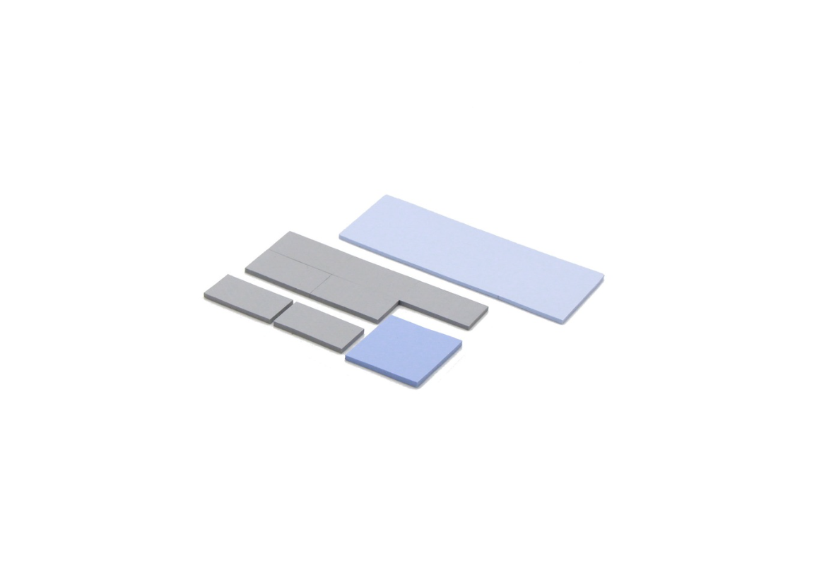
For the majority of rectifier module and BBU power supply interfaces, BN-filled silicone pads are the appropriate default. They combine the conductivity range required for telecom power applications — 5.0 to 10.0 W/m·K in commercial formulations — with production process simplicity, consistent thickness, and long-term stability characteristics that suit sealed, non-serviceable enclosures.
The key advantage over grease in telecom applications is dimensional stability. A BN-filled pad maintains its thickness and interface position across years of continuous operation without pump-out or migration. For a module that will not be opened for five to ten years, this predictability is worth more than the marginal conductivity advantage that grease offers at initial assembly.
Medium hardness formulations — Shore 00 40–60 — are appropriate for most rectifier interfaces where the heatsink surface is machined and the clamping arrangement is bolt-based. Softer formulations accommodate surface variation better but carry higher compression set risk under the sustained loads typical of continuously operating telecom equipment.
Phase change materials
PCMs offer a genuine performance advantage at high heat flux interfaces — power amplifier modules in RRU and AAU equipment, high-density rectifier switching devices — where the thermal budget is tight and every degree of junction temperature margin matters. Their ability to conform fully at operating temperature produces lower interface resistance than equivalent-conductivity pads in assemblies with surface variation.
The trade-off is assembly process complexity. PCMs require controlled pre-heating during assembly or rely on the first operational temperature cycle to achieve their working viscosity. For high-volume telecom equipment production, this adds a process step that pad-based solutions avoid. PCMs are worth the process investment at interfaces where their performance advantage justifies it — primarily the highest heat flux locations in RRU and AAU power amplifier modules.
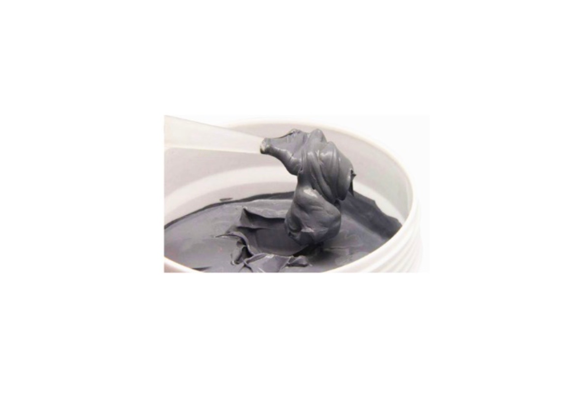
Thermal grease
Grease delivers good initial thermal performance and is widely used in telecom power equipment designs that were specified before the long-term stability requirements were fully understood. For new designs targeting 10–15 year sealed service life, grease is difficult to justify at primary interfaces.
The pump-out mechanism under sustained thermal load is well documented in telecom equipment field returns. A rectifier running at full load 24 hours a day accumulates thermal stress equivalent to years of intermittent industrial operation in a fraction of the calendar time. Grease that would survive five years of intermittent operation may show measurable pump-out in two years of continuous telecom duty.
Grease remains acceptable in telecom equipment where the interface is accessible for periodic maintenance — some indoor central office equipment falls into this category — or where the service life target is shorter than typical infrastructure deployments.
Gap fillers
Dispensed gap fillers become relevant in telecom enclosure designs where the gap between components and the enclosure wall or heatsink is irregular or varies significantly across the assembly. Cast aluminum enclosures used in some outdoor base station equipment have surface flatness that is less controlled than machined heatsink surfaces, making gap filler a practical choice where pad contact would be incomplete.
1K silicone-based gap fillers in the 3.0 – 5.0 W/m·K range cover most secondary interface requirements in telecom power equipment. For primary switching device interfaces where higher conductivity is needed, 2K formulations with BN filling reach 5.0 – 7.0 W/m·K and are appropriate where the dispensing process can be controlled to the bond line thickness consistency required.
Comparison table
| TIM Type | Typical W/m·K | Long-Term Stability | Assembly Process | Best Suited For |
|---|---|---|---|---|
| BN-filled silicone pad | 5.0 – 10.0 | High | Simple, consistent | Rectifier and BBU primary interfaces |
| Phase change material | 3.0 – 7.0 | High | Pre-heat required | High heat flux RRU/AAU interfaces |
| Thermal grease | 3.0 – 8.0 | Low–Medium | Dispensing required | Serviceable or short-life designs only |
| Gap filler (1K/2K) | 2.0 – 7.0 | Medium–High | Dispensing required | Irregular surfaces, cast enclosures |
Outdoor Base Station Equipment: Additional Requirements
Temperature extremes
The operating temperature range for outdoor base station equipment spans conditions that indoor telecom specifications do not address. Cold climate deployments — northern Europe, Canada, northern China — require reliable operation at −40°C ambient. Tropical and desert deployments combine high ambient temperatures with solar loading on outdoor enclosures, driving internal temperatures to 85–90°C during peak conditions.
The TIM must remain functional and maintain adequate contact across this full range. At the cold extreme, silicone-based materials retain flexibility at −40°C and below — this is one of the practical advantages of silicone over non-silicone formulations in outdoor equipment, where the wide temperature range of silicone-based pads (−40°C to +200°C in most commercial formulations) covers the full deployment envelope without requiring special low-temperature variants.
At the high temperature extreme, the TIM's rated operating temperature must be verified against the worst-case internal enclosure temperature under solar loading, not just the specified ambient. A TIM rated to +150°C with an 85°C internal enclosure temperature has 65°C of margin — adequate for most deployments. A TIM rated to +130°C in the same enclosure has only 45°C of margin, which may be insufficient when accounting for measurement uncertainty and abnormal operating conditions.
Humidity and condensation resistance
Outdoor enclosures that are not hermetically sealed experience internal humidity variation as ambient conditions change. Condensation on internal surfaces occurs when warm humid air enters an enclosure and the enclosure subsequently cools. Over years of operation, this cyclic humidity exposure affects materials that are not resistant to moisture absorption or hydrolysis.
Standard silicone-based thermal pads have good moisture resistance and are not significantly affected by the humidity conditions in outdoor base station enclosures. Confirm the moisture resistance rating for any alternative TIM type being considered for outdoor use — some acrylic-based silicone-free formulations are more sensitive to moisture than silicone-based equivalents.
Vibration and mechanical shock
Outdoor base station equipment on rooftops and towers is subject to wind-induced vibration and occasional mechanical shock from installation, maintenance, and extreme weather events. At TIM interfaces, vibration introduces cyclic shear loading in addition to the compressive load from assembly clamping.
Medium to firm pad hardness — Shore 00 45–60 — provides better resistance to vibration-induced displacement than very soft formulations. The pad should be firmly clamped within the assembly so that vibration does not cause relative movement between the pad and the mating surfaces. For interfaces in high-vibration locations — equipment mounted directly to antenna masts or tower structures — verify that the clamping arrangement provides adequate restraint against the expected vibration levels.
How outdoor requirements change the specification
The combination of wide temperature range, humidity exposure, and vibration requirements narrows the practical TIM options for outdoor base station equipment compared to indoor telecom applications. The wide operating temperature range effectively requires silicone-based formulations. Vibration resistance favors medium-hardness pads over very soft materials. Long service life without maintenance access eliminates grease from primary interfaces.
For most outdoor base station power equipment, BN-filled silicone pads in the 5.0 – 8.0 W/m·K range with medium hardness, rated to −40°C minimum and 150°C maximum, represent the practical default specification. Departures from this default — softer pads for surface accommodation, higher conductivity for power amplifier interfaces — should be justified by specific assembly requirements rather than adopted as general improvements.
Common TIM Specification Mistakes in Telecom Power Design
Specifying grease in sealed enclosures with 10+ year service life targets
This is the most consequential single mistake in telecom power TIM specification, and it remains common because grease performs well in short-term testing and qualification. The failure mode — pump-out under continuous thermal load over years — does not appear in a standard qualification test cycle. It appears in field returns two to four years into deployment, when the equipment is in service at a remote site and the failure is expensive to diagnose and repair. The solution is to validate long-term behavior before committing to a grease specification, not after the first field failures appear.
Using indoor-rated TIM specifications for outdoor base station equipment
Indoor telecom TIM specifications are typically validated across a narrower temperature range — often −20°C to +85°C — that does not cover the full outdoor deployment envelope. Applying these specifications to outdoor equipment without verifying the low-temperature flexibility and high-temperature stability across the full −40°C to +90°C range creates a gap between specification and deployment conditions. For outdoor equipment, require explicit validation data across the full outdoor temperature range from the supplier.
Ignoring compression set data for long-life applications
Compression set is often treated as a minor footnote in TIM datasheets rather than a primary selection parameter. For a telecom rectifier running continuously for ten years, the accumulated compression set in the TIM layer is a real contributor to end-of-life thermal resistance. A 15% compression set on a 1.0mm pad means the bond line is 0.15mm thicker at end of life than at initial assembly — a meaningful change in the thermal resistance budget for a tight design. Request and evaluate compression set data at operating temperature for any TIM being considered for long-life telecom applications.
Selecting TIM based on initial performance without long-term aging data
Datasheet thermal conductivity values and qualification test results describe material behavior at the beginning of service life. For telecom applications where the equipment will run continuously for a decade, initial performance data is necessary but not sufficient. Long-term aging data — thermal resistance after 2000+ hours at operating temperature, mechanical properties after extended thermal cycling — is the information that determines whether a material is a reliable specification for telecom use. Require this data from suppliers before approving a material for production, not as a follow-up after qualification.
Conclusion
TIM selection for telecom power equipment is fundamentally different from standard power electronics specification because the dominant requirement is long-term stability under continuous operation, not peak thermal conductivity. A material that performs well in initial qualification but degrades under ten years of continuous full-load operation at elevated temperature is not a telecom-grade specification, regardless of what its datasheet says.
The practical starting point for most rectifier and BBU power supply interfaces is a BN-filled silicone pad in the 5.0 – 8.0 W/m·K range, selected for its combination of thermal performance, dimensional stability, and wide operating temperature range. For outdoor base station equipment, verify the full −40°C to +90°C temperature range, humidity resistance, and vibration behavior in addition to the thermal specification. For high heat flux power amplifier interfaces in RRU and AAU equipment, phase change materials offer a performance advantage worth the additional process complexity.
Validate long-term behavior through supplier aging data and accelerated life testing before committing to a production specification. For telecom infrastructure that will run for a decade without maintenance access, the time invested in proper material qualification is returned many times over in avoided field failures.
If you are working through TIM selection for a telecom power application and need material recommendations or samples for evaluation.
Contact TaxoTape® to discuss TIM selection for your telecom power application →
FAQ
Q: How do I request long-term aging data if my TIM supplier's datasheet doesn't include it?
Ask directly for thermal resistance measurements at 1,000, 2,000, and 5,000 hours of continuous operation at your expected maximum interface temperature. Suppliers who position materials for telecom or other long-life industrial applications should have this data available even if it is not published in the standard datasheet — if a supplier cannot provide any long-term aging data on request, treat that as a signal the material has not been characterized for continuous-duty applications.
Q: Is BN-filled silicone pad always the right choice over PCM for rectifier interfaces?
Not always. BN-filled pads are the practical default for most rectifier and BBU interfaces due to their simpler assembly process and adequate performance across the 5.0–8.0 W/m·K range. PCM becomes the better choice specifically at high heat flux interfaces — typically above 15–20 W/cm² — where the thermal budget is tight enough that PCM's lower bond line thickness produces a meaningful junction temperature improvement. For standard rectifier switching devices with adequate thermal margin, the added assembly complexity of PCM is usually not justified.
Q: What compression set threshold should I use for a 10-year telecom deployment?
As a general reference, request compression set data at your operating temperature for at least 1,000 hours, and look for values below 15–20% at that duration. Since most datasheets do not test to full 10-year equivalent exposure, ask your supplier whether they have a validated aging model or longer-duration data (2,000+ hours) that can be extrapolated with reasonable confidence. Absent any long-term data, treat compression set values above 20% at 1,000 hours as a reliability risk for decade-long sealed deployments.
Q: Does outdoor base station equipment always require silicone-based TIM?
In practice, yes for most applications — the −40°C to +200°C operating range of standard silicone-based pads is difficult to match with silicone-free alternatives, which typically top out around −20°C to +150°C. Silicone-free is only necessary when outgassing is a specific concern, such as optical components sharing the sealed enclosure. For standard rectifier and power amplifier interfaces without adjacent optical components, silicone-based pads remain the practical default for outdoor deployments.